– 4 –
LED1
LED2
SW2
3. Since it is adjusted by rotating the volume VR6, check the position of the volume. Prepare a small slotted
screwdriver.
4. Set the roll paper.
5. Use the tip of a thin object to turn off the DIP switch DSW 1-4.
6. Press the SW2 switch on the control panel while turning the power switch ON.
7. Rotate the volume VR6 using micro screwdriver, to adjust it to a position whereat both the LED1(green LED) and
the LED2 (red LED) lamps light.
8. When the position where both LEDs for LED1/LED2 light cannnot be found by adjusting VR6, Adjust VR6 to the
position where the LED2 lights and LED1 extinguishes.
9. Turn the power OFF.
10. Turn the DIP switch DSW1-4 to its original setting of ON.
This completes the paper near end sensor adjustment.
Fig. 1-4 Control Panel
Содержание TUP900 Series
Страница 1: ...THERMAL PRINTER TUP900 SERIES TECHNICAL MANUAL SECOND EDITION ...
Страница 11: ... 9 Fig 2 2 Lubricated Areas TMP942 B 1 2 4 5 5 2 3 4 B C C D D A A ...
Страница 12: ... 10 Fig 2 3 Lubricated Areas PR921 B B C 7 C A A 7 8 8 6 ...
Страница 15: ...B TUP942 B B 16 11 15 11 5 10 6 15 14 12 22 23 17 17 18 19 20 7 12 8 9 15 13 14 14 3 2 13 14 14 12 14 4 ...
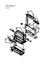
Страница 17: ... 15 2 Mehcanism Base Unit 2 1 Disassembly Drawing A TUP992 1 12 3 13 7 11 2 8 9 8 9 12 10 5 11 12 12 13 4 6 12 ...
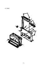
Страница 18: ... 16 B TUP942 11 2 10 5 11 12 12 13 4 6 12 ...
Страница 34: ... 32 2 5 Flash Flash EPSON BA T500 Compatible Manufacturer molex ...
Страница 35: ... 33 3 5 ...
Страница 36: ... 34 4 5 Pitch Thermistor ...
Страница 37: ... 35 5 5 ...
Страница 45: ... 43 8 Serial Interface Board 25pin 8 1 Circuit Diagram ...
Страница 47: ... 45 9 Serial Interface Board 9pin 9 1 Circuit Diagram ...
Страница 49: ... 47 10 USB Interface Board 10 1 Circuit Diagram ...
Страница 51: ... 49 11 Parallel Interface Board 11 1 Circuit Diagram ...


