Stanley CT10016N Скачать руководство пользователя страница 10

10 CT10 USER MANUAL

TO CHANGE THE CURRENT SETTING:

1. Remove the hydraulic hose coupling from the return port 

on the tool, if one is installed. When making the change from 

CC to OC, hydraulic fluid may be trapped in the tool, prevent

-

ing complete movement of the adapter. Remove the return 

coupling to allow the hydraulic fluid to escape.

2. Loosen the 2 setscrews on the cylinder.

3. Turn the adapter until it stops:

• counter clockwise (CCW) to change to closed center  

(creates gap)

• clockwise (CW) to change to open center (closes gap) 

4. Tighten the two setscrews.
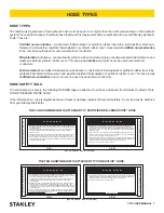
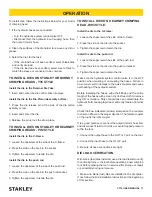
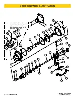
DIE INSTALLATION

One die is installed in the crimping head (Retainer Die Yoke 

or C-frame) and the other die is installed onto the ram or 

die piston assembly, depending on the model. See below to 

identify the style of crimping head you have. Refer to the parts 

illustrations in this manual for more detailed reference.

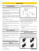
Open-Center (no gap)

Adapter

Cylinder

Trigger Handle

Top View of Tool

PRE-OPERATION

Careful inspection of the tool and hydraulic system before 

startup is important for safe, reliable operation of the tool. 

The following items should be checked daily at the start and 

the end of each work shift.

1. Make sure the proper dies are securely in place. Operating 

the tool without dies can deform the crimping heads. Refer to  

Die Installation for instructions.

2. Connect hoses. Wipe all hose couplers with a clean, lint-

free cloth before making connections. Dirty couplers can 

contaminate the hydraulic lines and prevent a good seal at 

the connection.

3. Check all fasteners for tightness.

4. Check the equipment for oil leaks. If leaks are observed, do 

not use the tool; have the equipment serviced before use.

5. Check the tool and hydraulic system for proper operation 

and performance. 

6. If the equipment does not appear to operate properly, have 

it serviced before use.

7. Periodically verify the crimping force of the tool. Refer to  

Die Load Verification.

SETUP AND TEST

Never operate the tool without dies. Operating without dies can 

deform the crimping head (retainer die yoke or C-frame).  

If this happens, the dies cannot be installed and the crimping 

head must be replaced.

Never install the dies while the hydraulic hoses are connected 

to the tool.

Verify the crimping force before operating the tool.

OPEN CENTER/CLOSED CENTER 

SETUP

The CT10 Hydraulic Crimping Tool can be configured for either 

open-center or closed-center operation. The current setting 

is easily determined by looking at the gap between the adapter 

and the cylinder:

Burndy Y35 & 30 mm Style

Retainer Die Yoke

Kearney WH3 Style

C-Frame

Stanley Y35 Style

Retainer Die Yoke

Kearney PH2 Style

C-Frame

OPERATION

Содержание CT10016N

Страница 1: ...CT10 HYDRAULIC CRIMPING TOOL USER S MANUAL Safety Operation and Maintenance 2014 Stanley Black Decker Inc New Britain CT 06053 U S A 58545 5 2017 Ver 11...

Страница 2: ......

Страница 3: ...y operation and routine maintenance instructions Stanley Hydraulic Tools recommends that servicing of hydraulic tools other than routine maintenance must be performed by an authorized and certified de...

Страница 4: ...s in an area accessible to the operator and mainte nance personnel This is the safety alert symbol It is used to alert you to potential personal injury hazards Obey all safety messages that follow thi...

Страница 5: ...ct clean or replace any part s if the hydraulic power source is connected Do not inspect or clean the tool while the hydraulic power source is connected Accidental engagement of the tool can cause ser...

Страница 6: ...NNECTORS DAILY FOR LEAKS DO NOT FEEL FOR LEAKS WITH YOUR HANDS CONTACT WITHALEAK MAY RESULT IN SEVERE PERSONAL INJURY I M P O R T A N T READ OPERATION MANUAL AND SAFETY INSTRUCTIONS FOR THIS TOOL BEFO...

Страница 7: ...HE HOSE AND FITTING WITH A CLEAN DRY ABSORBENT CLOTH TO REMOVE DIRT AND MOSISTURE AND TEST HOSE FOR MAXIMUM ALLOWABLE CURRENT LEAKAGE IN ACCORDANCE WITH SAFETY DEPARTMENT INSTRUCTIONS SEE OTHER SIDE D...

Страница 8: ...8 10 2750 190 3 4 19 Return SAE 100R1 16 1000 69 SAE 100R7 12 1250 86 9 12 34 45 100 200 30 60 3 4 19 Pressure SAE 100R17 12 3000 230 NA NA NA 1 25 4 Return SAE 100R1 16 1000 69 NA NA NA 13 16 49 60 u...

Страница 9: ...13 gpm 15 23 lpm 26 34 lpm 34 40 lpm 42 49 lpm 1500 psi 1500 psi 1500 psi 1500 psi 103 bar 103 bar 103 bar 103 bar 2100 2250 psi 2100 2250 psi 2200 2300 psi 2100 2250 psi 145 155 bar 145 155 bar 152 1...

Страница 10: ...rating the tool without dies can deform the crimping heads Refer to Die Installation for instructions 2 Connect hoses Wipe all hose couplers with a clean lint free cloth before making connections Dirt...

Страница 11: ...rew at the side of the C frame 2 Press the stub on the die into the socket 3 Tighten the capscrew to retain the die Install the die to the push rod 1 Loosen the capscrew at the side of the push rod 2...

Страница 12: ...on CHECK POWER SOURCE Using a calibrated flowmeter and pressure gauge check the hydraulic power source at the tool s input port Make sure the system maintains an operating flow in the range of 3 9 gpm...

Страница 13: ...f the connector SHUTDOWN 1 Move the hydraulic system control valve to the off posi tion 2 Disconnect the hydraulic hoses from the tool first the input supply hose then the output return hose 3 Insert...

Страница 14: ...s couplings and other parts with replacement parts recommended by Stanley Hydraulic Tools Supply hoses must have a minimum working pressure rating of 2500 psi 172 bar Do not exceed the rated flow Refe...

Страница 15: ...etracts when trigger is squeezed Hoses connected to wrong ports on tool Connect input supply line to IN port Connect output return line to OUT port Tool under crimps Die load less than 10 tons 9072 kg...

Страница 16: ...Crimping Force 12 tons 1650 psi 10 886 kg 114 bar Pressure Range 1650 2500 psi 114 172 bar Flow Range 3 9 gpm 11 34 lpm Optimum Flow 8 gpm 30 lpm Porting 3 8 NPT Hose Whips Couplers No Weight 17 lbs...

Страница 17: ...CT10 USER MANUAL 17 NOTES...

Страница 18: ...28 34 11 26 25 32 33 22 8 31 1 4 2 44 THIS IS A NEWER MODEL CYLINDER HEAD AND C FRAME THE CYLINDER HEAD ITEM 38 HAS A THREAD DIAMETER OF M60X1 5 METRIC AND A THREAD LENGTH OF 1 100 CHECK THESE DIMENSI...

Страница 19: ...29 51183 1 Trigger 30 52534 2 Setscrew 31 58439 1 Adapter 32 58440 1 Retaining Ring 33 58441 1 Sleeve 34 58442 1 Oil Tube 35 58480 1 Piston 36 58485 1 O Ring 37 58493 1 Cylinder 38 67276 1 Cylinder H...

Страница 20: ...HE CYLINDER HEAD ITEM 38 HAS A THREAD DIAMETER OF M60X1 5 METRIC AND A THREAD LENGTH OF 1 100 CHECK THESE DIMENSIONS ON YOUR CYLINDER HEAD BEFORE ORDERING PARTS TO MAKE SURE YOU ARE ORDERING THE CORRE...

Страница 21: ...35 58442 1 Oil Tube 36 58480 1 Piston 37 58481 1 Cylinder 38 67276 1 Cylinder Head See Note 1 39 58485 1 O Ring Item No Part No Qty Description 40 58499 1 Sticker 41 58583 1 T Seal 42 58594 1 Retaini...

Страница 22: ...22 CT10 USER MANUAL CT10056N PARTS ILLUSTRATION 41 40 44 10 6 38 43 17 20 9 22 21 19 12 27 22 39 18 42 16 2 4 1 34 8 24 36 35 28 29 37 5 13 25 32 15 14 7 30 3 3 23 11 31 26 33 46...

Страница 23: ...m Nut 22 12430 2 Capscrew 23 16556 1 Spring 24 18050 1 Back Up Ring 25 21424 1 Relief Valve 26 22147 2 Capscrew 27 34133 1 Spring Plunger 28 38622 1 Valve Sleeve 29 39925 1 Compression Spring 30 39939...

Страница 24: ...24 CT10 USER MANUAL CT10066AN PARTS ILLUSTRATION 40 7 38 48 10 37 42 21 22 3 15 18 20 49 50 51 41 39 2 23 5 1 33 9 24 35 34 27 28 36 6 14 13 8 4 52 29 4 19 11 25 31 12 26 30 6 1...

Страница 25: ...Trigger 32 52534 2 Setscrew 33 58439 1 Adapter 34 58440 1 Retaining Ring 35 58441 1 Sleeve 36 58442 1 Oil Tube 37 58480 1 Piston 38 58481 1 Cylinder 39 58485 1 O Ring Item No Part No Qty Description...

Страница 26: ...Stanely Hydraulic Tools 3810 SE Naef Road Milwaukie Oregon 503 659 5660 Fax 503 652 1780 www stanleyhydraulics com...

Отзывы: