13
Fig.18
CYC - ST
A
T
:
Remove link between
T
erminal 1 and T
erminal
31. Connect cyc - st
at on
to T
erminals 1 & 31.
The following diagrams illustrate the
dif
ferent types of central heating sys-
tems to which this appliance can be
connected, but are not to be used as
working drawings.
NOTE:
W
e
strongly advise the use of
pipe lagging and also the use of a
frost thermost
at if the inst
allation is
likely to be exposed to situations
where the temperature will dip to a
level consistent with frost.
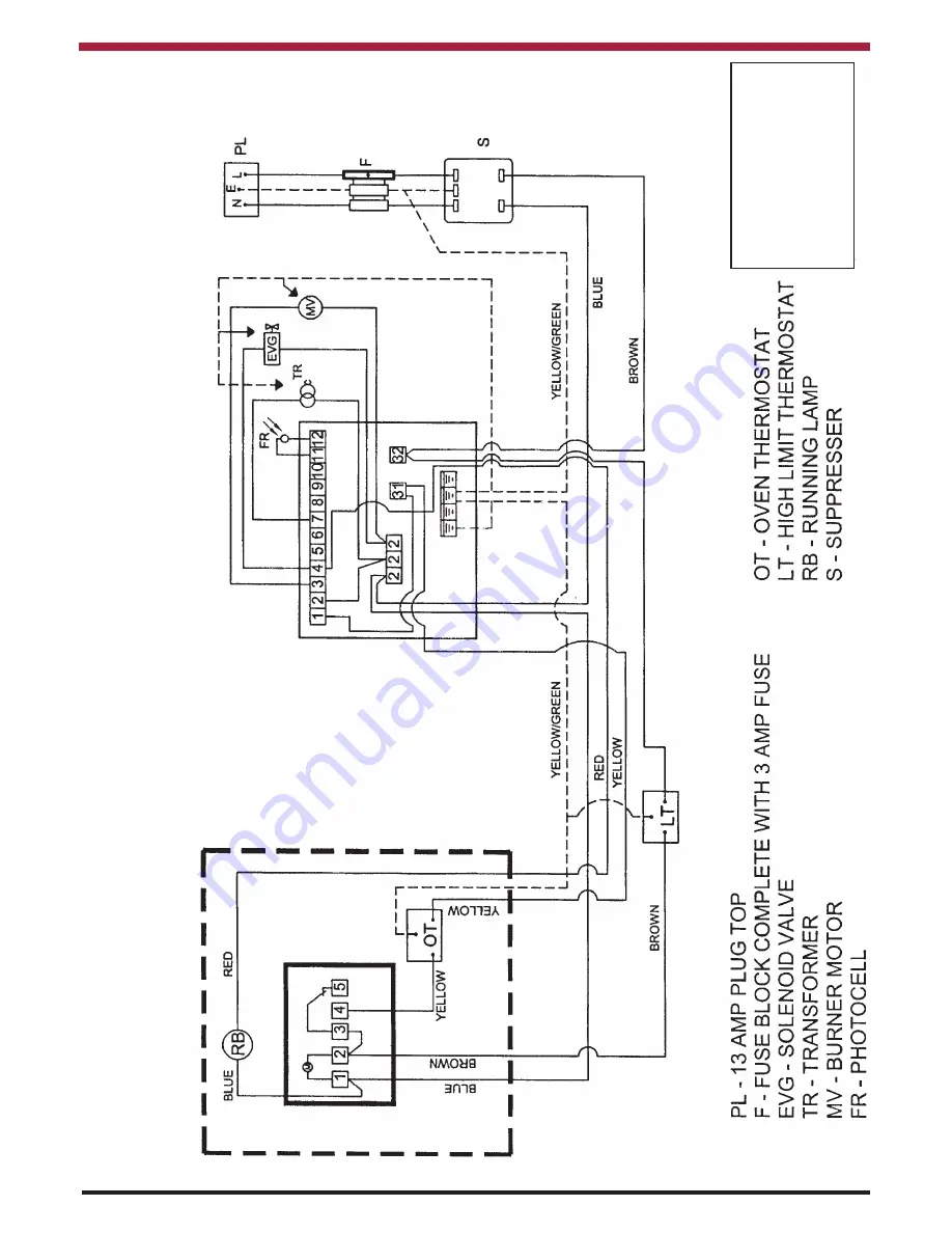
WIRING DIAGRAM
- MECHANICAL
CLOCK


