Standalone DSP Скачать руководство пользователя страница 30

30

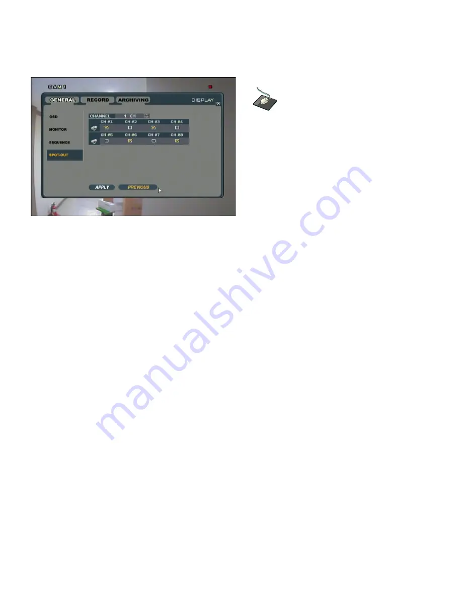
DISPLAY : SPOT-OUT continued

To change the behavior of the spot monitor outputs, first choose the spot CHANNEL to modify,

And then use the 

CURSOR KEYS 

and 

ENTER 

button to move around the channels and tick to include 

or un-tick to exclude from the spot out sequence.

When all changes have been made, highlight APPLY and press 

ENTER 

to save.

SYSTEM SETUP

SYSTEM SETUP

Click the camera number that user want. 

Содержание DSP

Страница 1: ...1 ...

Страница 2: ...ller description 14 Connect Power On 15 Live display configure 16 Division screen 16 Live display edit mode 17 Digital zoom 18 Sequence 19 Panic Recording 19 Key Lock Function 20 PTZ Camera control 20 SYSTEM SETUP 22 Display 23 OSD 23 Monitor 24 Sequence 25 Spot Out 29 Camera 31 Camera Title 31 Color Setup 32 PTZ Setup 33 Motion Sensor 34 Sound 37 Audio 37 Buzzer 38 ...

Страница 3: ...fication 49 Disk Manage 50 RECORD MENU 51 Recording operations 51 Timer Motion Setup 52 Parameter 52 Schedule 55 Alarm setup 58 Panic setup 59 SEARCH 60 Time Search 60 Event Search 63 Archiving 65 Remote Client Setup 68 Client software installation 68 Client software organization 70 Explanation of Function keys 71 Create a connect group 72 Detail Setup 73 Additional Configuration 75 ...

Страница 4: ...tion of function keys 77 Quick Search 78 Archiving 79 Still Shot 79 Log Viewer 80 Backup Player 80 Print 81 Event Viewer 81 Remote Recording Setup 82 Record 82 Camera 83 Sound 83 Event Sensor 84 System 85 WEB CONNECTION SETUP 86 ...

Страница 5: ...block any of the air vents on the DVR Adequate protection against lightning strikes and power surges must be installed to prevent damage to the DVR Any safety warnings on the DVR and in these instructions must be adhered to If cleaning is necessary shutdown the DVR and disconnect power first Use a soft dry cloth only never use any abrasive cleaners Do not attempt to service or repair the DVR as op...

Страница 6: ...up log for full traceability REMOTE CONNECTION Software is provided to allow remote connection to up to 4 DVRs in one session Depending on user level Full DVR control is available over the internet as well as the ability to remotely configure the DVR Alarm outputs on the DVR can be remotely triggered over the internet COMPREHENSIVE RECORDING SETUP Recording can be scheduled alarm activated or moti...

Страница 7: ...aneously Support is also provided for up to 4 spot monitors and each spot monitor output can be programmed in the DVR setup LIVE DISPLAY The DVR displays single or multi screen images and also has several sequence modes standard and user definable CONFIGURATION BACKUP All configuration settings on the DVR can be saved to USB memory stick or a PC file remotely The saved data can then be uploaded to...

Страница 8: ... ORGANIZATION SYSTEM ORGANIZATION NETWORK Camera Alarm Sensor Relay Out AV Monitor Remote Client PC Image Printer Video In Video Out TCP IP Alarm Input Out Remote Controller AVI Backup WEB Client USB USB mouse ...

Страница 9: ...9 SYSTEM CONTENTS SYSTEM CONTENTS Basic Contents Remote Controller User s Manual Remote Client Program Install CD AAA Battery X 2 Power Cable Option Contents HDD CD RW USB Memory ...

Страница 10: ...y JOG RING When playback is paused used to move footage forwards or backwards frame by frame HOLD Locks the current function of the SHUTTLE WHEEL so it can be released USB ports Supports a wide variety of USB memory stick for archive system setting backup and firmware upgrade An additional USB port is also provided on the rear panel CURSOR KEYS ENTER and RETURN buttons Used for navigating setup me...

Страница 11: ...e SHUTTLE WHEEL so it can be released USB ports Supports a wide variety of USB memory stick for archive system setting backup and firmware upgrade Also support USB mouse for control CURSOR KEYS ENTER and RETURN buttons Used for navigating setup menus search and archive screens Also used when the DVR is in PTZ mode CHANNEL SELECTION BUTTONS Used to display individual channels in live display and Pl...

Страница 12: ...OUTPUTS Up to 4 audio inputs and one audio output can be connected as necessary ALARM INPUTS Up to 16 alarm inputs can be connected and configured as high or low inputs with common ground Connection to external telemetry devices panic button and alarm reset ALARM OUTPUTS Up to 16 alarm outputs can be connected and configured as high or low outputs with common ground VGA VGA main monitor connection...

Страница 13: ...an be connected as necessary AUDIO INPUTS OUTPUTS Up to 4 audio inputs and one audio output can be connected as necessary ALARM INPUTS OUTPUTS Up to 4 alarm inputs and outputs can be connected and configured as high or low inputs with common ground VGA S VIDEO VGA main monitor connection to a PC monitor or plasma screen Can be used simultaneously with the COMPOSITE and S VIDEO main monitor connect...

Страница 14: ... be set different ID then Remote controller set each ID on DVR Can control all DVRs on one Remote controller by each ID Navigation Buttons Used for Playback Control Menu Navigation and PTZ Focus Control ID ID Button Select DVR ID How to set ID on the remote controller Press the ID button then displayed INPUT ID statement Press the set ID and Press the RETURN button The default ID is 01 For DVR ID ...

Страница 15: ...ecks the status of hard drives and the CDRW DVR RW drive After startup diagnostics are complete the operator must logon to the system The default user name is ADMIN Using the CHANNEL SELECTION buttons key in the default password of 1234 and press the ENTER button The DVR begins normal operation and shows the default display of all 16 channels The status bar at the bottom of the screen shows curren...

Страница 16: ...s All the display modes are static with the exception of the sequence mode In this mode the sequence symbol is displayed and each channel is shown in full screen for a set period of time default 3 sec before switching to the next channel The sequence runs indefinitely until a different display mode is chosen Click the right mouse button on the Live Display screen and Click the DISPLAY menu Click t...

Страница 17: ...the DISPLAY button to choose the multi screen mode to edit and then press ENTER to select LIVE DISPLAY EDIT MODE In this example the default 8 screen mode displays channels 1 8 To display channel 10 instead of channel 5 Using the CHANNEL SELECTION buttons press number 5 channel 5 changes to a blue screen LIVE DISPLAY LIVE DISPLAY ...

Страница 18: ...main display area shows the zoomed portion To adjust the zoom level turn the SHUTTLE WHEEL clockwise to increase zoom or anticlockwise to decrease zoom To move the zoom area around the image use the CURSOR KEYS to adjust the position of the zoom square Press the RETURN button to return to normal live display mode LIVE DISPLAY LIVE DISPLAY Click the right mouse button on the Live Display screen and...

Страница 19: ...equence Panic Recording Panic recording will override all standard recording settings to provide by default continuous recording on all channels Press the PANIC button The top right of the display shows a red square only to indicate that the DVR is in panic recording mode Press the PANIC button again to return to normal cording mode Click the right mouse button on the Live Display screen and Click...

Страница 20: ...lay screen and Click the KEY LOCK menu Double click on the Password tap then the Virtual Keyboard will be appeared Then click the password and click the button PTZ Camera Control Speed domes and other telemetry devices connected to the DVR can be fully controlled from the front panel In live display mode press the PTZ button To select a camera to control use the CHANNEL SELECTION buttons Pan and t...

Страница 21: ...r SEQ buttons to decrease or increase the swing number Press PAUSE to program the preset or ENTER to call an existing swing Press RETURN to exit PTZ mode and return to live view LIVE DISPLAY LIVE DISPLAY PTZ Camera Control continued Click the SWING menu ...

Страница 22: ...ER button is used to select and change a particular item and the RETURN button is used to cancel a change or exit from a particular setup screen To setup all main system functions highlight SYSTEM SETUP and press ENTER SYSTEM SETUP SYSTEM SETUP Click the right mouse button on the Live Display screen and Click the SETUP menu Double click on the Password tap then the Virtual Keyboard will be appeare...

Страница 23: ...If false motion recording is occurring the operator can use this feature to determine and rectify the cause in realtime OFF normal display mode ACTIVE areas where motion is detected are highlighted with colored blocks INACTIVE areas where no motion is detected are highlighted with colored blocks MOTION COLOR The color of the blocks displayed when MOTION SENSOR DISPLAY is set to ACTIVE or INACTIVE ...

Страница 24: ...tion detection will cause the associated channel to display full screen MOTION POP UP DWELL Determines how long the full screen popup is displayed after motion detection If motion continues the popup screen is displayed constantly DISPLAY MODE The DVR output can be optimized for display on a VGA or AV CRT monitor To change any of these settings highlight MONITOR and press ENTER to select Use the C...

Страница 25: ...perator to define a custom sequence using mixed multi screen views and any desired channels To add a new sequence highlight ADD and press ENTER Sequence title is highlighted press ENTER to bring up the virtual keyboard and key in a name or reference number for the new sequence SYSTEM SETUP SYSTEM SETUP Click the SEQUENCE menu Click the ADD menu ...

Страница 26: ...yboard case and access symbols use To exit press RETURN SYSTEM SETUP SYSTEM SETUP Double click on the SEQUENCE TITLE tap Virtual Keyboard will be appeared Then click the any name and click the button Set ACTIVATION to ON highlight SAVE and press ENTER to display the sequence programming screen Click on the ACTIVATION tap and click button for select ON OFF ...

Страница 27: ...n the correct screen type is displayed use the CHANNEL SELECTION button to enter the channels required for each portion of the multi screen Note Only one instance of each channel can be displayed To remove a channel press the appropriate CHANNEL SELECTION button again SYSTEM SETUP SYSTEM SETUP Double click on the box then the box color change to the orange When click each time the split screen cha...

Страница 28: ...o 16 different sequence screens can be created To finish editing the sequence press RETURN and then ENTER to save exit SYSTEM SETUP SYSTEM SETUP When finish selecting the camera number click on the screen Then next split screen appears Make the split screen and select camera number To finish right mouse click on the screen Click the SAVE EXIT menu ...

Страница 29: ...lit screen activate DISPLAY SPOT OUT The DVR has 4 SPOT MONITOR OUTPUTS Each one displays a full screen sequence of particular channels depending on the settings configured in this menu For each spot monitor the operator can decide which channels are displayed For example spot 1 could display channels 1 4 spot 2 could display channels 5 8 and so on Click the SPOT OUT menu and click the camera chan...

Страница 30: ...pot CHANNEL to modify And then use the CURSOR KEYS and ENTER button to move around the channels and tick to include or un tick to exclude from the spot out sequence When all changes have been made highlight APPLY and press ENTER to save SYSTEM SETUP SYSTEM SETUP Click the camera number that user want ...

Страница 31: ...ed in live display but continues to be recorded TITLE For each camera a title of up to 11 characters can be set using the virtual keyboard SYSTEM SETUP SYSTEM SETUP Click the CAMERA menu Click the CAMERA TITLE menu and click the ON OFF menu on the COVERT menu Then click the button for ON OFF Click the CAM No on the TITLE menu and change the camera name ...

Страница 32: ...k the COLOR SETUP menu and click the value on the BRIGHTNESS CONTRAST TINT and COLOR menu The selected channel is displayed in full screen BRIGHTNESS CONTRAST TINT and COLOUR can be changed as necessary To modify a different channel highlight CAMERA and choose the desired channel Press RETURN when all changes are complete DISPLAY COLOR SETUP continued Click the each value by button ...

Страница 33: ...d for each channel by selecting the icon and pressing ENTER Note that some settings such as AUTO FOCUS may not be compatible with particular PTZ equipment If this is the case changing this value will have no effect on PTZ control Click the PTZ SETUP menu and click the each value on the ADDRESS PROTOCOL and BAUD RATE menu Change the value by button Click the button and change the detail value by bu...

Страница 34: ...he operator to define which areas of the image are monitored for motion detection Light blue grid squares represent detection areas grey grid squares are ignored The area on the right shows that motion will be detected across the entire image SYSTEM SETUP SYSTEM SETUP Click the MOTION SENSOR menu and click the value on the SENSITIVITY menu Change the value by button Click the button ...

Страница 35: ...UP SYSTEM SETUP To select or deselect specific areas press ENTER to bring up the green cursor square in the top left of the display Move the cursor using the CURSOR KEYS to the first corner of the area to be set and press ENTER the cursor turns orange To quick select or deselect the entire grid click the right mouse button and click the SELECT ALL or DESELECT ALL menu Drag the grid by the left mou...

Страница 36: ...vice versa Repeat the above sequence as necessary to mask off or include other areas of the image Once the detection area has been defined press RETURN and choose SAVE EXIT to save the area and return to the motion setup menu Please note a motion detection recording schedule must be defined in the RECORD MENU described on page 51 Click the right mouse button and select the SAVE EXIT menu ...

Страница 37: ...DIO OUTPUT AUDIO MONITORING CHANNEL Specify which one of the 4 AUDIO INPUTS is routed to the AUDIO OUTPUT NETWORK AUDIO TX When set to ON live and playback audio is transmitted to a remote PC connection NETWORK AUDIO RX When set to ON allows a remote PC connection to send audio back to the DVR Click the SOUND menu Click the AUDIO menu and click the ON OFF menu Then click the button for ON OFF ...

Страница 38: ...IR REMOTE When set to ON each command received from the IR remote is confirmed by a beep SYSTEM SETUP SYSTEM SETUP SYSTEM To setup the various system options highlight SYSTEM and press ENTER Click the BUZZER menu and click the ON OFF menu Then click the button for ON OFF Click the SYSTEM menu ...

Страница 39: ...ER SETUP If the DVR is connected to the Internet the time and date can be accurately set by selecting SYNC and pressing ENTER TIME ZONE SETUP should be set according to the region that the DVR is used in D S T When set to ON the DVR will automatically adjust the time by one hour on the relevant date in spring and autumn DATE TIME Click the DATE TIME menu and click the ON OFF menu Then click the bu...

Страница 40: ...ers IP ADDRESS If DHCP is not being used the IP address can be manually set GATEWAY If DHCP is not being used the gateway IP address can be manually set SUBNET MASK If DHCP is not being used the subnet mask can be manually set 1ST DNS SERVER If DHCP is not being used the first DNS server can be manually set 2ND DNS SERVER If DHCP is not being used the second DNS server can be manually set DDNS SER...

Страница 41: ...be entered for the mail function to operate correctly The username must not contain spaces SYSTEM USER MANAGEMENT By default the DVR is configured with a user ID of ADMIN belonging to the ADMIN group and with a password of 1234 As well as the ability to add new users existing user details can be modified To modify user details highlight the user with the green cursor and press ENTER SYSTEM SETUP S...

Страница 42: ...N MANAGER or USER E MAIL Enter the users email address if email notification is required E MAIL NOTIFICATION Enable or disable email notifications for this particular user Please note For security reasons it is recommended that the ADMIN user password is changed as soon as possible SYSTEM SETUP SYSTEM SETUP SYSTEM USER MANAGEMENT continued For edit double click on the each tap After changing click...

Страница 43: ... live view settings Playback and DVR setup is not available MANAGER Members of this group can adjust live view settings and playback recorded footage including covert cameras ADMIN Members of this group have full control over the DVR including setup Please note Any user can be deleted except the default ADMIN user SYSTEM SETUP SYSTEM SETUP SYSTEM USER MANAGEMENT continued Click the ADD menu Enter ...

Страница 44: ...AC address SYSTEM NAME A system name of up to 10 characters can be defined It is used so that notification emails can be identified F W UPDATE Firmware updates may be released periodically to enhance system performance and add extra features The operator can upgrade the firmware using a USB memory stick FACTORY DEFAULT If settings have been changed which cause erratic behavior the factory default ...

Страница 45: ... DVR on stack each DVR must have unique ID for control by Remote controller PROTOCOL Must be set by Control Device BAUD RATE Must be set to match the baud rate of the PTZ controller SYSTEM SETUP SYSTEM SETUP EVENT SENSOR To setup the various event handling options highlight EVENT SENSOR and press ENTER Click the EVENT SENSOR menu Click the CONTROL DEVICE menu And select the SYSTEM ID PTZ Protocol ...

Страница 46: ...n be adjusted as desired Determines the behavior of each of the 16 alarm inputs OPERATION Alarm inputs can be enabled or disabled TYPE Alarm inputs can be set as normally open or normally closed SYSTEM SETUP SYSTEM SETUP Click the HDD EVENT menu and click the DRIVE SMART ALARM and CHECK INTERVAL value Then click the value by button to change Click the ALARM INPUT menu and click the OPERATION and T...

Страница 47: ...fter it has been triggered TYPE Can be set to high 0V to 5V when activated or low 5V to 0V when activated HDD EVENT Determines whether a hard drive event triggers the alarm output Action settings ALARM Determines whether alarm inputs will trigger the alarm output VIDEO LOSS Determines whether video loss on any of the selected channels will trigger the alarm output MOTION Determines whether motion ...

Страница 48: ...uzzer sounds after it has been triggered HDD EVENT Determines whether a hard drive event sounds the buzzer Action settings ALARM Determines whether alarm inputs will sound the buzzer VIDEO LOSS Determines whether video loss on any of the selected channels will sound the buzzer MOTION Determines whether motion detection on any of the selected channels will sound the buzzer Remember to select APPLY ...

Страница 49: ...tings ALARM Determines whether alarm inputs will send an email VIDEO LOSS Determines whether video loss on any of the selected channels will send an email MOTION Determines whether motion detection on any of the selected channels will send an email Email settings must also be configured in MAIL and USER MANAGEMENT settings described on page 42 SYSTEM SETUP SYSTEM SETUP Click the EMAIL NOTIFICATION...

Страница 50: ...ive used shown in live display will always be 99 When set to OFF the DVR will stop recording when the disk becomes full FORMAT If necessary all footage can be erased from the DVR using this option Please note When RECORD TIME LIMIT is set the percentage of HDD used shown in live display mode may never reach 99 For example if the total HDD capacity of the DVR allows for a recording time of 4 days u...

Страница 51: ...n continuous recording mode this setting determines the amount of footage that is always recorded before an event occurs motion detection alarm input etc POST EVENT RECORDING TIME When the DVR is not in continuous recording mode this setting determines the amount of footage that is always recorded after an event occurs motion detection alarm input etc RECORD MENU RECORD MENU Click the RECORD menu ...

Страница 52: ...l hour Note that when SCHEDULE MODE is set to WEEKLY each day of the week can also be selected SCHEDULE This section determines at what times the DVR will record and whether it is continuous recording or motion detection RECORD MENU RECORD MENU Click the TIMERMOTION SETUP menu PARAMETER To change PARAMETER settings highlight TIMER MOTION SETUP and press ENTER Ensure PARAMETER is highlighted in yel...

Страница 53: ... period Example To change the recording settings between 09 00 and 18 00 Use the CURSOR KEYS to move the green cursor to the 09 00 position and press ENTER The cursor changes to orange to show the start position Use the CURSOR KEYS to stretch the orange cursor across to the 18 00 position RECORD MENU RECORD MENU PARAMETER continued Click the TIMEBAR that user want Drag the time that user want ...

Страница 54: ...set for each channel QUALITY Four different picture recording qualities can be set for each channel AUDIO If audio devices are connected to the DVR any audio channel can be assigned to any of the video channels The default settings for all channels is 352 x 288 7FPS HIGHEST quality Note The DVR supports a maximum recording rate across all channels of 112 frames per second at 352x288 resolution As ...

Страница 55: ... highlighted in purple Press ENTER to display the green cursor Example To set all channels to motion detection recording only between 18 00 and 00 00 Use the CURSOR KEYS to move the green cursor to the 18 00 position and press ENTER The cursor changes to orange to show the start position RECORD MENU RECORD MENU Click the SCHEDULE menu Click the Time and Channel ...

Страница 56: ...KEYS to stretch the orange cursor across and down to select all channels between 18 00 and 00 00 RECORD MENU RECORD MENU Drag the Time and Channel by left mouse Press ENTER highlight MOTION and press ENTER again After drag click the Motion ...

Страница 57: ...t different recording schedules for individual channels and time periods The schedule screen has 3 symbols to show the different recording modes Dark blue blocks No scheduled or motion recording Light blue blocks The DVR will record continuously Half light blue block The DVR will only record when motion is detected RECORD MENU RECORD MENU ...

Страница 58: ...LE This section determines at what times the DVR will monitor the alarm inputs and activate recording Please refer to Timer motion setup on page 52 for details on setting up PARAMETER and SCHEDULE Alarm activated recording can be used in conjunction with timer motion recording For example the DVR could be configured to record continuously at a low frame rate set in timer motion setup and then incr...

Страница 59: ...nic recording mode the DVR will override all other recording settings and record continuously on all channels at the settings configured here RECORD MENU RECORD MENU Click the PANIC SETUP menu Select the Size Frame Quality and audio ...

Страница 60: ...d for quick access to recorded footage The calendar displayed on the left shows the current month Days highlighted in green have recorded footage The timeline on the right shows a 24 hour status of all channels for the selected day Light blue areas show recorded footage Click the right mouse button on the Live Display screen and Click the SEARCH menu Double click on the Password tap then the Virtu...

Страница 61: ...y Press ENTER to choose the day and move to the timeline Drag the time bar by left mouse TIME SEARCH continued Use the CURSOR KEYS to move the timeline cursor left or right to select the time segment required Each movement of the timeline cursor increases or decreases the time by 15 minutes The currently selected time is displayed above the calendar Press ENTER to begin playback from the selected ...

Страница 62: ...screen to choose another time and date press RETURN To exit the search screen and go back to live view repeatedly press RETURN Turning steadily anticlockwise will reverse play by up to 64 times When the SHUTTLE WHEEL is released playback is paused If the HOLD button is pressed and released during SHUTTLE WHEEL operation the last shuttle function is held even if the wheel is released When playback ...

Страница 63: ... select SEARCH BY EVENT and press ENTER Various filters can be used to limit the number of events displayed Using the CURSOR KEYS and ENTER button select the FROM and TO date time and the events and channels required Click the right mouse button on the Live Display screen and Click the SEARCH menu Double click on the Password tap then the Virtual Keyboard will be appeared Then click the password a...

Страница 64: ...E WHEEL JOG RING and playback buttons can be used as normal To stop playback and return to live view mode repeatedly press RETURN Note The event log search contains the following selectable entries ALARM When ticked all alarm input events are displayed for the chosen date range TIMER When ticked scheduled recording operations are displayed for the chosen date range MOTION When ticked all motion de...

Страница 65: ...te around the Archiving screen To change any value or setting Press ENTER to change the green cursor to orange Use the up and down CURSOR KEYS to change the value Press ENTER to accept the value or RETURN to cancel To change a tick box setting press ENTER to toggle on or off ARCHIVING ARCHIVING Click the right mouse button on the Live Display screen and Click the ARCHIVING menu Double click on the...

Страница 66: ... the archive set EVENT When selected the event log for the particular archive time period is included Once all the desired archive options have been selected highlight the START button and press ENTER The DVR displays a list showing the exact information to be archived and the total archive size If the ORIGINAL SIZE is larger than the available space on the backup media the END TIME of the archive...

Страница 67: ...ive Once extracted the footage is copied to CD or USB Note that depending on the amount of footage selected for archive the extracting and burning process may take some time during which the DVR cannot be used Normal recording is unaffected by the archive process ARCHIVING ARCHIVING ...

Страница 68: ... of PTZ cameras In addition playback remote setup audio talkback local backup and remote alarm triggering can all be achieved REMOTE CLIENT SETUP REMOTE CLIENT SETUP Client Software Installation Insert the CD supplied with the DVR into your PC s CD ROM drive The install process will begin automatically and display the following screen Click Next to continue Click Next to begin installation ...

Страница 69: ...allation is successful Two icons are created on the PC desktop Remote Agent is the main software package BackupPlayer is the software to view archive footage from the DVR To begin using the remote client software double click the icon on the desktop or click Start Programs RemoteAgent DVR RemoteAgent The main remote client window is displayed ...

Страница 70: ...utton to access remote playback SETUP button to configure DVR connections DVR SETUP button to adjust DVR settings remotely DROP DOWN LIST to select a DVR connection CONNECT button DISCONNECT button DISPLAY button to choose 1 4 9 or 16 screen display SEQUENCE button MANUAL SWITCH button FULL SCREEN button SAVE TO AVI button EVENT VIEWER button PTZ CONTROL button ...

Страница 71: ... software to change or check the setting DVR SETUP Button Entering the connected DVR to change or check the setting DROP DOWN LIST Select the group to connect CONNECT Button Connect DVR DISCONNECT Button Disconnect DVR DISPLAY Button Change the division screen to 1 4 9 or 16 SEQUENCE Button Change the live screen automatically MANUAL SWITCH Button Change the live screen manually by mouse click FUL...

Страница 72: ...ber of connection groups Each connection group can consist of up to 4 DVRs To create a connection group click the SETUP button to display the Local configuration screen In the Group window on the left right click Site and choose Add Group Enter a name to easily identify the connection group and click OK The new group is created ...

Страница 73: ...amera Assignment window specific channels of the DVR can be allocated to the remote client display channels Using the drop down lists under DVR select which channels are displayed and in what position To ignore certain channels leave the drop down as x In this case only channels 1 4 from the selected DVR will be displayed Note only one instance of each channel can be selected Each connection group...

Страница 74: ... is transmitted to the remote client software during live display In Connection retries choose the number of times the remote client will attempt to connect before giving an error Finally click ADD to save all the details To add up to three more DVRs to this group simply repeat the steps from the previous page in Enter DVR details To create another connection group repeat the steps from the previo...

Страница 75: ...For best results leave set at the default of Video Renderer Overlay mixer and GDI are provided only for backwards compatibility with older PCs Video Mode Define the sequence time between each channel when in sequence mode Also determines the full screen popup time when an alarm is triggered on the DVR Video Display For best results leave Quality improve selected Saving directory Specify the locati...

Страница 76: ...TE CLIENT SETUP LIVE button DVR SETUP button SETUP button DIVISION SCREEN buttons ARCHIVING button P64 STILL SHOT button LOG VIEWER button BACKUP PLAYER EXCUTE button PRINT button EVENT VIEWER button CAMERA SELECTION button QUICK SEARCH button SEARCH CONTROLLER button SEARCH BAR ...

Страница 77: ...ion screen to 1 4 9 or 16 BACKUP Button Can backup by channel including audio STILL SHOT Button Can save current image LOG VIEWER Button Can see all log records BACKUP PLAYER EXECUTE button Execute the backup player PRINT Button Can print current image EVENT VIEWER Button Can see all event records CAMERA SELECTION Button Can select camera number QUICK SEARCH Button To playback quickly select date ...

Страница 78: ... footage Choose the required date by selecting and then adjusting the date value using the up and down arrows As different dates are selected the TIMELINE changes to show the status of recorded footage for that particular date Use the mouse to drag the CURSOR to the required time The exact time selected is displayed under the date Click to begin playback from the selected date and time To select r...

Страница 79: ...audio For convenience choosing Select All will highlight all available channels including audio for archiving Click OK to begin archiving data to the PC hard drive During playback a still image can be save to the local PC hard disk by clicking the SNAPSHOT button Specify the file location file name and choose BMP or JPG format Click Save The snapshot image is saved in the same style as the current...

Страница 80: ...ntrols under the display can be used to adjust playback direction and speed To search for an event and playback the recorded footage press the EVENT SEARCH button Choose the Start time and End time Select which events to include in the search and click Search The event log for the selected time period is displayed Select an event click Go to timeline and then click OK Click to begin playback from ...

Страница 81: ...nted on the local PC printer by clicking the PRINT button The printed image is in the same style as the currently selected screen display for example quad screen During playback any live events detected on the DVR are sent to the remote client event log To display this click the CURRENT EVENT LOG button ...

Страница 82: ... CLIENT SETUP RECORD Record Operations Schedule Mode Select Weekly or Daily Pre Event Recording Time Record image including setting time before event happened 0 5 Second Post Event Recording Time Record image including setting time after event happened 5 180Second Alarm Recording Schedule Click the SET Button to set Alarm Recording Setup the size rec rate quality and audio Continuous Motion record...

Страница 83: ...Name Color Setup the Bright Contrast Tint and Color PTZ Setup the PTZ camera address Protocol Baud rate and Properties for detail setup Motion Area Setup the motion sensitive and motion area SOUND Live Audio Setup Live Audio On Off Audio Monitoring Channel Select audio channel for live Network Audio TX Choose the Audio transmission Network Audio RX Choose the Audio receive ...

Страница 84: ...ted relay time duration 5seconds to 5minutes or Until key in Buzzer out Check the Buzzer out event Alarm Video loss Motion Buzzer Select the buzzer On Off for buzzer sound Duration Setup the Buzzer time duration 5seconds to 5minutes or Until key in Disk Event Select Buzzer On Off for Buzzer when HDD happened any event Keypad Select buzzer sound On Off when key input Remote Ctrl Select buzzer sound...

Страница 85: ...m Info Check the DVR System information SMTP Type the SMTP server name and user ID password to use E mail notification Users Add or delete any user Network Speed Select the network speed Disk Overwrite Select the On Off for using disk overwrite Record Time Link Select the recording period ...

Страница 86: ...the Internet Explorer Address Bar If when user use the DDNS input the URL like below http 00115f349021 dvrlink net Then a dialog will appear to confirm download of an ActiveX control Please click the CONFIRM or CONTINUE button WEB CONNECTION SETUP WEB CONNECTION SETUP ...

Страница 87: ...87 Input the default Port 6100 and User ID ADMIN Password 1234 correctly Then set the Camera Assignment like below picture Click the MODIFY button and OK button WEB CONNECTION SETUP WEB CONNECTION SETUP ...

Страница 88: ...88 Click the CONNECTION button WEB CONNECTION SETUP WEB CONNECTION SETUP ...

Страница 89: ...89 ...

Отзывы: