264707 / 944260310010
2017-12-01·BA00·III·en·00
Mounting and installation
11
EN
EN
EN
EN
EN
EN
EN
EN
EN
EN
EN
EN
EN
EN
EN
EN
EN
EN
EN
EN
EN
EN
EN
EN
EN
CPU module for Zone 2
Series 9442/35
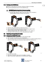
6.1.2 Mounting on the 9496/35 base
19647E00
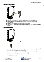
Mount the base (see 9496/35 operating instructions).
Hang (1) the CPU module in the bottom of the base and swivel it in (2).
Use the safety screws to fasten the CPU module.
Tighten the safety screws with a tightening torque of 1.5 to 1.9 Nm (3).
The 9442/35 CPU module may not be connected to slot 3 (right)!
6.2
Replacing and upgrading the module
6.2.1 Replacing the 9442/35 CPU module
Switch off the power supply to the IS1+ Remote I/O System.
Disconnect the connection lines for communication.
Use a screwdriver (for T20 hexalobular internal screws) to unscrew the safety screw (1),
swivel the module forward and out (2) and disconnect it from the base (3).
19648E00
Insert the new module.
Reconnect connection lines (see the "Installation" chapter).
Switch on the power supply (see the "Commissioning" chapter).
Before mounting the CPU module, set the bus address on the base
(see the operating instructions for the 9496/35 base).
DANGER! Explosion hazard due to insecure mounting!
Non-compliance may result in serious or even fatal injury.
Use the safety screws to fasten the CPU module. Use a screwdriver
(T20 hexalobular internal screws) for this process.
1
2
3
1
2
3
Содержание 9442/35-10-00
Страница 2: ......

