background image

Zubehör und Ersatzteile

32

207321 / 941160310190

2018-04-16·BA00·III·de·04

Feldgeräte-Koppler 8 Spurs Zone 2 Ex i

Reihe 9411/24

DE
DE
DE
DE
DE
DE
DE
DE
DE
DE
DE
DE
DE
DE
DE
DE
DE
DE
DE
DE
DE
DE
DE
DE
DE

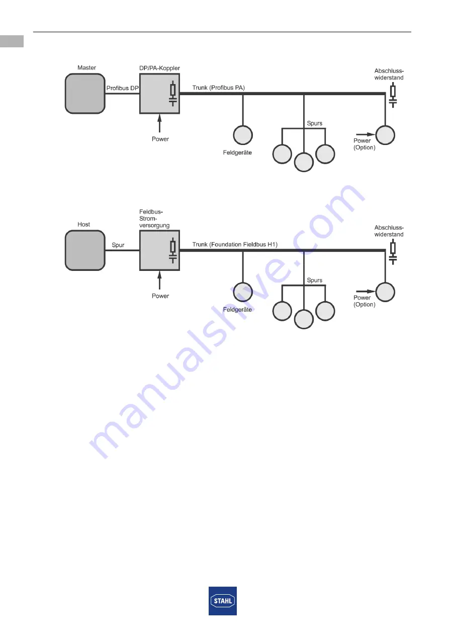
Struktur eines Profibus-PA-Segments

11462E00

Struktur eines Foundation-Fieldbus-H1-Segments

11463E00

Содержание 9411/24 Series

Страница 1: ...EN DE EN DE EN DE EN DE EN DE Betriebsanleitung Operating instructions Additional languages www r stahl com DE EN Feldgeräte Koppler 8 Spurs Zone 2 Ex i Zone 2 Ex i Field Device Coupler 8 Spurs Reihe 9411 24 Series 9411 24 ...

Страница 2: ......

Страница 3: ...DE DE DE DE DE DE DE DE DE DE DE DE DE DE DE DE DE DE DE DE DE DE DE DE DE Betriebsanleitung Additional languages www r stahl com DE Feldgeräte Koppler 8 Spurs Zone 2 Ex i Reihe 9411 24 ...

Страница 4: ...n und Änderungen 6 4 Funktion und Geräteaufbau 6 4 1 Funktion 7 4 2 Geräteaufbau 9 5 Technische Daten 10 6 Projektierung 14 6 1 Beispiele für die Struktur von Feldbus Segmenten 14 6 2 Nachweis der Eigensicherheit 16 6 3 Kabellängen für Trunk und Spurs 16 6 4 Erdung Schirmung 16 6 5 Abschlusswiderstand Terminator 19 7 Transport und Lagerung 19 8 Montage und Installation 20 8 1 Maßangaben Befestigun...

Страница 5: ...tenblatt Weiterführende Literatur zur Erdung und Schirmung IEC EN 60079 14 2013 Explosionsgefährdete Bereiche Teil 14 Projektierung Auswahl und Errichtung elektrischer Anlagen Abschnitt 16 2 2 3 PROFIBUS Planung Design Version 1 13 Order No 8 011 8 012 Language German English PROFIBUS Montage Cabling and Assembly Version 1 14 Order No 8 021 8 022 Language German English Fieldbus FoundationTM Syste...

Страница 6: ...ahr des Schadens Folgen der Gefahr Ergreifen von Gegenmaßnahmen zum Vermeiden der Gefahr bzw des Schadens Symbol Bedeutung Tipps und Empfehlungen zum Gebrauch des Geräts Gefahr durch explosionsfähige Atmosphäre GEFAHR Gefahren für Personen Nichtbeachtung der Anweisung führt zu schweren oder tödlichen Verletzungen bei Personen WARNUNG Gefahren für Personen Nichtbeachtung der Anweisung kann zu schwe...

Страница 7: ...n Normen beschrieben wird IEC EN 60079 14 Projektierung Auswahl und Errichtung elektrischer Anlagen IEC EN 60079 17 Prüfung und Instandhaltung elektrischer Anlagen IEC EN 60079 19 Gerätereparatur Überholung und Regenerierung 3 3 Sichere Verwendung Vor der Montage Sicherheitshinweise in dieser Betriebsanleitung lesen und beachten Sicherstellen dass der Inhalt dieser Betriebsanleitung vom zuständige...

Страница 8: ...ls Stromkreise der Zündschutzart Ex i betrieben werden Inbetriebnahme Wartung Reparatur Inbetriebnahme und Instandsetzung nur durch qualifizierte und autorisierte Personen siehe Abschnitt Qualifikation des Personals durchführen lassen Vor Inbetriebnahme sicherstellen dass das Gerät unbeschädigt ist Nur Wartungsarbeiten durchführen die in dieser Betriebsanleitung beschrieben sind 3 4 Umbauten und Ä...

Страница 9: ...ieldbus H1 und Profibus PA Bei nicht eigensicherem Trunk Anschlüsse Ex nA Bei eigensicheren Spurs Ex i und FISCO zum Anschluss eigensicherer Feldgeräte Einsatz von Feldgeräte Koppler Trunk und Spurs 03673E00 Feldgeräte Koppler Zone 2 Ex i Zone 0 Zone 1 Zone 2 Zone 21 Zone 22 nicht explosions gefährdeter Bereich Ohne Feldgehäuse 9411 24 310 41 9411 24 320 41 9411 24 330 41 Nicht zulässig Nicht zulä...

Страница 10: ...enzung auf 50 mA ausgestattet Ein Abschlusswiderstand ist eingebaut Dieser kann mit einer Brücke aktiviert oder deaktiviert werden Kabelschirme können wahlweise kapazitiv oder direkt geerdet werden Trunk und Spurs können unterschiedlich geerdet werden siehe Kapitel Erdung und Schirmung Die am Feldgeräte Koppler anliegende Trunk Spannung wird auf Unterspannung überwacht Ihr Status wird mit einer LE...

Страница 11: ... und für Brücke zur Aktivierung des Abschlusswiderstands Arbeiten an Ex nA Anschlüssen unter Spannung ist in Zone 2 nicht zulässig 2 LEDs Betriebsanzeige LED PWR für Power und ERR für Error 3 Trennwand Die Trennwand gewährleistet den vorgeschriebenen Fadenabstand zwischen Ex e und Ex i Anschlussklemmen 4 LEDs Betriebsanzeige LEDs für Spur 1 8 5 Erdungsbolzen Erdungsbolzen für Erdung 6 Parkposition...

Страница 12: ...G Ex nA ia Ga IIC T4 Gc E II 1 D Ex ia Da IIIC Bescheinigungen und Zertifikate Bescheinigungen IECEx ATEX Brasilien INMETRO Kanada cFM Kasachstan TR Russland TR USA FM Weißrussland TR Schiffszertifikate DNV GL Sicherheitstechnische Daten CENELEC je Spur FISCO Power Supply Max Spannung Uo 15 7 V Max Strom Io 245 mA Max Leistung Po 960 mW Max anschließbare Kapazität Co für IIC IIB 476 nF 2878 nF Max...

Страница 13: ...nungs bereich 16 32 V Unterspannungs überwachung U 16 V Spurs stromlos Max Nenn Eingangsstrom Trunk IN OUT 2 A Max Spannungsabfall Trunk IN OUT 60 mV Max Trunk Eingangstrom Max Verlustleistung 1 8 W Betriebsanzeige LED grün PWR U 16 V von Trunk Verpolschutz ja Max Anzahl Feldgeräte Koppler 4 pro Trunk Feldbus Abschluss widerstand Hinweis Im Feldgeräte Koppler ist ein zuschaltbarer Feldbus Abschlus...

Страница 14: ...ung 12 V Max Innenwiderstand 65 Ω Max Kurzschlussstrom 50 mA Betriebsanzeige je Spur LED gelb S1 S8 Erdung der Kabelschirme Trunk und Spurs Direkte Erdung auf Schirmschiene optional Kapazitive Erdung Spurs über 4 7 nF an Klemme S Erdungsbolzen M6 Kapazitive Erdung Trunk über 2 35 nF an Klemme S Erdungsbolzen M6 Fehlererkennung Kurzschluss Spur 42 50 mA Anzeige Kurzschluss je Spur LED gelb S1 S8 bl...

Страница 15: ...hutzart Gehäuse IP30 Ex i Klemmen IP20 Ex e Klemmen IP30 Abdeckung geschlossen das Einbaugehäuse darf im Ex Bereich unter Spannung geöffnet werden Gewicht 0 735 kg Brandfestigkeit UL 94 HB Montage Installation Einbaubedingungen Montageart auf DIN Schiene EN 50022 NS 35 15 NS 35 7 5 oder Montageplatte Einbaulage senkrecht oder waagrecht Technische Daten 3 polig Schirm Schraub klemmen abziehbare Sch...

Страница 16: ...chaltschrank so aufbauen und einrichten dass er immer innerhalb des zulässigen Temperaturbereichs betrieben wird Technische Daten 06799E01 Ex i Foundation Fieldbus H1 oder Profibus PA Feldgeräte Foundation Fieldbus H1 oder Profibus PA Trunk Power Management nicht Ex i TERM T1 T2 TRUNK IN S TRUNK OUT S S SPUR 4 S SPUR 3 S SPUR 2 S SPUR 1 Ex i Ex i Ex i nicht Ex i I I I I S S S S SPUR 5 SPUR 6 SPUR ...

Страница 17: ...t Aus dieser Abzweigdose verlaufen die Trunks zu den einzelnen Feldgeräte Kopplern 06588E00 Host Trunk nicht Ex i Spurs Ex i Spur Feldbus Strom versorgung Feldgerätekoppler Ex e Ex i Feldgerätekoppler Ex e Ex i Feldgerätekoppler Ex e Ex i Feldgerätekoppler Ex e Ex i Host redundant Trunk Länge 1 Trunk Länge 2 Trunk Länge 3 Trunk Länge 4 Spur Länge 1 m Splice Host Trunk nicht Ex i Spurs Ex i Spur Fe...

Страница 18: ...purs Die Grundlage zur Bemessung der Kabellängen für Trunk und Spurs ist die IEC 61158 2 Annex B ohne Berücksichtigung des Explosionsschutzes Bei der Kabelauslegung folgende Punkte beachten Die maximale Länge aller Kabel alle Trunks alle Spurs pro Segment darf 1900 m nicht überschreiten Die tatsächlichen Trunk und Spur Längen können wegen des Spannungsabfalls kürzer sein Generell gilt Spurs immer ...

Страница 19: ...gen siehe Abbildung Nur durch die schlüssige Verbindung mit allen 4 Schrauben wird das Gerät mit dem Potentialausgleich verbunden es ist kein gesonderter Anschluss erforderlich 19380E00 6 4 2 Kabelschirme erden Trunk Kabelschirme erden Die Kabelschirme des Trunks können am Feldgeräte Koppler kapazitiv über die Klemme S 2 35 nF oder direkt über die Schirmschiene als Zubehör erhältlich geerdet werde...

Страница 20: ...Kabelschirme auf zwei Arten geerdet werden kapazitiv über die Klemmen S 4 7 nF und den Erdungsbolzen gemäß IEC EN 60079 14 2014 Abschnitt 16 2 2 3 Punkt direkt über die optional erhältliche Schirmschiene als Zubehör erhältlich und den Erdungsbolzen entspricht der Multi Point Erdung bei Verfügbarkeit eines hochwertigen Potentialausgleichs gemäß IEC EN 60079 14 2014 Abschnitt 16 2 2 3 Punkt b Kapazi...

Страница 21: ...en Ein Trunk Abschlusswiderstand ist in jedem Feldgeräte Koppler fest installiert Zum Aktivieren des Trunk Abschlusswiderstands wird die Brücke aus der Parkposition des Feldgeräte Kopplers entfernt und an den Klemmen des Klemmenblocks TERM angeschlossen Befindet sich der Feldgeräte Koppler am Ende des Trunks d h die Klemmen am Klemmenbock TRUNK OUT sind nicht belegt dann muss der Abschlusswidersta...

Страница 22: ... eine geeignete Schutzart bieten Bei Einsatz in Zone 2 und im sicheren Bereich ist ein Gehäuse mit mindestens IP54 erforderlich Bei Einsatz in Zone 22 ist ein Gehäuse mit mindestens IP64 erforderlich GEFAHR Explosionsgefahr durch falsche Installation des Geräts Nichtbeachten führt zu schweren oder tödlichen Verletzungen Installation strikt nach Anleitung und unter Berücksichtigung der nationalen S...

Страница 23: ...ahr beim Öffnen des Gehäuses unter gefährlichen Umgebungsbedingungen Nichtbeachten kann zu schweren oder tödlichen Verletzungen führen Hinweisschilder anbringen Bei Einbau in ein Ex e Schutzgehäuse Hinweisschild nach IEC EN 60079 7 anbringen Nicht unter Spannung öffnen Bei Einbau in ein Schutzgehäuse entsprechend EN 61241 1 für Zone 22 Hinweisschild anbringen Nicht in explosionsfähiger Staubatmosp...

Страница 24: ...n Bereichen z B in einem normalen Schaltschrank oder offenen Gestell Montage mit Gehäuse Installation in explosionsgefährdeten Bereichen z B in einem Schutzgehäuse von R STAHL der Reihen 8146 8125 8150 oder in einem bescheinigten Gehäuse eines anderen Herstellers 8 2 2 Montage der Schirmschiene Im Auslieferungszustand sind die Schirmanschlussklemmen und die Verbindungsleitung zum Erdanschlussbolze...

Страница 25: ...hirmschiene mit Erdpotential verbinden Die Erdung der Schirmschiene kann auf zwei Wege erfolgen Direkt Über Erdungsbolzen z B bei Einbau in ein Metallgehäuse mit Schrauben 19395E00 Eine Leitung mit Durchmesser min 4 mm2 verwenden und mit Schrauben gegen Lockern sichern Anzugsdrehmoment 1 5 Nm Die mitgelieferte Verbindungsleitung kann in diesem Fall entfallen 19397E00 Die Schirmschiene mit der mitg...

Страница 26: ...äts oder angeschlossener Feldgeräte Nichtbeachten führt zu schweren oder tödlichen Verletzungen Sicherheitstechnische Werte des Geräts und angeschlossener Feldgeräte entsprechend der nationalen Installationsvorschriften prüfen GEFAHR Explosionsgefahr durch geöffneten Gehäusedeckel bei aktiviertem Feldbus Nichtbeachten führt zu schweren oder tödlichen Verletzungen Vor dem Öffnen des Gehäusedeckels ...

Страница 27: ...digen Leiter in Klemmen einführen und festklemmen Aderendhülsen mit geeignetem Werkzeug aufpressen Die Leiterisolation muss bis an die Klemmen heranreichen Klemmen mit vorgegebenem Anzugsdrehmoment festziehen Anzugsdrehmoment 0 5 0 6 Nm Trunk anschließen TRUNK IN Klemmen S TRUNK OUT Klemmen S TRUNK IN Eingangsleitung des Trunks TRUNK OUT Abgangsleitung zum Weiterschleifen des Trunks Klemme S Schir...

Страница 28: ...chten Nicht benutzte Leitungseinführungen verschließen Bescheinigte Stopfen für die Leitungseinführungen verwenden Stopfen verwenden deren Größe zum Klemmbereich der jeweiligen Leitungseinführung passen Offene Gehäusebohrungen verschließen Zugelassene und bescheinigte Verschlussstopfen verwenden Verschlussstopfen verwenden die die Gehäuseöffnungen sicher verschließen Gehäuse schließen Gehäusedecke...

Страница 29: ... Liegt Spannung am Trunk an leuchtet die LED PWR Ist ein Spur in Betrieb wird dies durch die entsprechende LED S angezeigt 10 2 Anzeigen Entsprechende LEDs am Gerät zeigen den Betriebszustand des Geräts an siehe auch Kapitel Funktion und Geräteaufbau GEFAHR Explosionsgefahr durch fehlerhafte Installation Nichtbeachten führt zu schweren oder tödlichen Verletzungen Gerät vor der Inbetriebnahme auf k...

Страница 30: ...ls korrekt anschließen Koppler tauschen Versorgungsspannung am Koppler prüfen LED ERR leuchtet interner Gerätefehler Koppler tauschen LED ERR leuchtet LED S1 S8 blinkt schnell Entsprechender Spur verursacht Überlast Gesamtstromaufnahme der angeschlossenen Feldgeräte 160 mA im Nennbetrieb Feldgerät am angezeigten Spur überprüfen und gegebenenfalls Feldgerät ersetzen LED ERR erloschen LED S1 S8 erlo...

Страница 31: ...bsprache mit R STAHL durchführen Dazu mit der zuständigen Vertretung von R STAHL Kontakt aufnehmen Für die Rücksendung im Reparatur bzw Servicefall steht der Kundenservice von R STAHL zur Verfügung Kundenservice persönlich kontaktieren oder Internetseite www r stahl com aufrufen Unter Support RMA Formular RMA Schein anfordern wählen Formular ausfüllen und absenden Bestätigung erfolgt Der R STAHL K...

Страница 32: ...tel verwenden Keine aggressiven Reinigungsmittel oder Lösungsmittel verwenden 13 Entsorgung Nationale und lokal gültige Vorschriften und gesetzliche Bestimmungen zur Entsorgung beachten Materialien getrennt dem Recycling zuführen Umweltgerechte Entsorgung aller Bauteile gemäß den gesetzlichen Bestimmungen sicherstellen 14 Zubehör und Ersatzteile HINWEIS Fehlfunktion oder Geräteschaden durch den Ei...

Страница 33: ...äte in den Feldbus ein und bewirkt die Impendanzanpassung zwischen Feldbus und Power Der Host verhält sich elektrisch wie ein Feldgerät Feldgerät Feldgeräte werden häufig aus dem Feldbus gespeist sie können aber auch eine eigene Stromversorgung haben 4 Leiter Gerät Host Der Host Anbieter Moderator ist das Gehirn in der Feldbusphysik In der Regel ist der Host ein Prozessleitsystem eine SPS oder ein...

Страница 34: ...8 04 16 BA00 III de 04 Feldgeräte Koppler 8 Spurs Zone 2 Ex i Reihe 9411 24 DE DE DE DE DE DE DE DE DE DE DE DE DE DE DE DE DE DE DE DE DE DE DE DE DE Struktur eines Profibus PA Segments 11462E00 Struktur eines Foundation Fieldbus H1 Segments 11463E00 ...

Страница 35: ...EN EN EN EN EN EN EN EN EN EN EN EN EN EN EN EN EN EN EN EN EN EN EN EN EN Operating instructions Additional languages www r stahl com EN Zone 2 Ex i Field Device Coupler 8 Spurs Series 9411 24 ...

Страница 36: ...ications and Alterations 6 4 Function and Device Design 6 4 1 Function 7 4 2 Device Design 9 5 Technical Data 10 6 Engineering 14 6 1 Examples of Fieldbus Segment Topologies 14 6 2 Proof of Intrinsic Safety 16 6 3 Cable Lengths for Trunk and Spurs 16 6 4 Earthing Shielding 16 6 5 EOL Resistor Terminator 19 7 Transport and Storage 19 8 Mounting and Installation 20 8 1 Dimensions Fastening Dimension...

Страница 37: ...s Data sheet Additional literature on earthing and shielding IEC EN 60079 14 2013 Explosive atmospheres Part 14 Electrical installations design selection and erection Section 16 2 2 3 PROFIBUS planning design version 1 13 Order No 8 011 8 012 Language German English PROFIBUS mounting cabling and assembly version 1 14 Order No 8 021 8 022 Language German English Fieldbus FoundationTM System Enginee...

Страница 38: ...NING CAUTION NOTICE Type and source of danger damage Consequences of danger Taking countermeasures to avoid the danger or damage Symbol Meaning Tips and recommendations on the use of the device Danger due to explosive atmosphere DANGER Danger to persons Non compliance with the instruction results in severe or fatal injuries to persons WARNING Danger to persons Non compliance with the instruction c...

Страница 39: ...ribed in the following standards IEC EN 60079 14 Electrical installations design selection and construction IEC EN 60079 17 Inspection and maintenance of electrical installations IEC EN 60079 19 Equipment repair overhaul and reclamation 3 3 Safe Use Before mounting Read and observe the safety notes in these operating instructions Ensure that the contents of these operating instructions are fully u...

Страница 40: ... with this protection type after being operated with circuits with other types of protection Commissioning maintenance repair Only have commissioning and repairs performed by qualified and authorised persons see Personnel qualification section Before commissioning make sure that the device is not damaged Perform only maintenance work described in these operating instructions 3 4 Modifications and ...

Страница 41: ...ation Fieldbus H1 and Profibus PA For non intrinsically safe trunks Ex nA connections For intrinsically safe spurs Ex i and FISCO to connect intrinsically safe field devices Use of field device couplers trunks and spurs 03673E00 Zone 2 Ex i field device coupler Zone 0 Zone 1 Zone 2 Zone 21 Zone 22 Non hazardous area Without field enclosure 9411 24 310 41 9411 24 320 41 9411 24 330 41 Not permissib...

Страница 42: ...EOL resistor is installed This can be activated or deactivated with a jumper Cable shields can either be capacitively or directly earthed Trunks and spurs can be earthed differently see the chapter Earthing and shielding The trunk voltage supplied to the field device coupler is monitored to ensure that no undervoltage occurs Its status is indicated by an LED Other LEDs indicate the status of the s...

Страница 43: ...or are protected by a hinged covering IP30 performing work on the Ex nA connections in Zone 2 is only permitted if de energised 2 LEDs PWR for Power and ERR for Error operation indication LEDs 3 Partition The partition guarantees prescribed spacing of lead wires between Ex e and Ex i connection terminals 4 LEDs Operation indication LEDs for spurs 1 to 8 5 Earth bolt Earth bolt for earthing 6 Park ...

Страница 44: ...6 ATEX E 004 X E II 3 1 G Ex nA ia Ga IIC T4 Gc E II 1 D Ex ia Da IIIC Certifications and certificates Certificates IECEx ATEX Brazil INMETRO Canada cFM Kazakhstan TR Russia TR USA FM Belarus TR Ship approval DNV GL Safety data CENELEC per spur FISCO Power Supply Max voltage Uo 15 7 V Max current Io 245 mA Max power Po 960 mW Max connectable capacitance Co for IIC IIB 476 nF 2878 nF Max connectabl...

Страница 45: ...ge range 16 to 32 V Undervoltage monitoring U 16 V spurs de energised Max rated input current Trunk IN OUT 2 A Max voltage drop Trunk IN OUT 60 mV Max rated trunk input current Max power dissipation 1 8 W Indication PWR LED green U 16 V from trunk Reverse polarity protection yes Max number of Field Device Couplers 4 per trunk Fieldbus terminator Note An integrated field device EOL resistor 100 Ω 1...

Страница 46: ...nal resistance 65 O Max short circuit current 50 mA Indication per spur Yellow LED S1 to S8 Earthing of cable shields trunk and spurs Direct earthing on the shield bus option Capacitive earthing spurs via 4 7 nF at terminal S earth bolt M6 Capacitive earthing trunk via 2 35 nF at terminal S earth bolt M6 Error detection Spur short circuit 42 to 50 mA Indication of short circuit per spur Yellow LED...

Страница 47: ...minals IP20 Ex e terminals IP 30 cover closed the installation enclosure may be opened in a hazardous area while connected to power Weight 0 735 kg Fire resistance UL 94 HB Mounting Installation Installation conditions Mounting type on DIN rail EN 50022 NS 35 15 NS 35 7 5 or mounting plate Mounting orientation vertical or horizontal Technical Data 3 pole shield Screw terminals Detachable screw or ...

Страница 48: ...age Install and adjust the cabinet in such a way that it is always operated within the permissible temperature range Technical Data 06799E02 Ex i Foundation Fieldbus H1 or Profibus PA Field devices Foundation Fieldbus H1 or Profibus PATrunk Power Management not Ex i TERM T1 T2 TRUNK IN S TRUNK OUT S S SPUR 4 S SPUR 3 S SPUR 2 S SPUR 1 Ex i Ex i Ex i not Ex i I I I I S S S S SPUR 5 SPUR 6 SPUR 7 SP...

Страница 49: ...trunks run from this junction box to the individual field device couplers 06588E00 Host Trunk not Ex i Spurs Ex i Spur Fieldbus power supply Field device coupler Ex e Ex i Field device coupler Ex e Ex i Field device coupler Ex e Ex i Field device coupler Ex e Ex i Host redundant Trunk length1 Trunk length2 Trunk length3 Trunk length4 Spur length 1 m Splice Host Trunk not Ex i Spurs Ex i Spur Field...

Страница 50: ...engths for Trunk and Spurs The basis for measuring cable lengths for the trunk and spurs is IEC 61158 2 Annex B without taking into account explosion protection Note the following points when laying cables The maximum length of all cables all trunks all spurs per segment must not exceed 1900 m The actual trunk and spur lengths can be shorter due to voltage drop The following generally applies Spur...

Страница 51: ...ee figure Only a frictional connection with all 4 screws can be used to connect the device with the equipotential bonding no separate connection is required 19380E00 6 4 2 Earth the Cable Shields Earthing trunk cable shields The cable shields of the trunk can be capacitively earthed to the field device coupler using the S terminal 2 35 nF or directly earthed using the shield bus available as acces...

Страница 52: ...two ways based on the equipotential bonding Capacitive connection using the S terminals 4 7 nF and earth bolt in accordance with IEC EN 60079 14 2014 Section 16 2 2 3 point Direct connection using the optionally available shield bus available as accessories and the earth bolt corresponds to multipoint earthing if high quality equipotential bonding is available in accordance with IEC EN 60079 14 20...

Страница 53: ...r A trunk EOL resistor is permanently installed in every field device coupler To activate the trunk EOL resistor the jumper is removed from the park position on the field device coupler and connected to the terminals on the TERM terminal block If the field device coupler is located at the end of the trunk i e the terminals on the TRUNK OUT terminal block are not being used the EOL resistor must be...

Страница 54: ...n in accordance with IEC EN 60079 0 An enclosure with at least an IP54 protection rating is required for use in Zone 2 and in safe areas An enclosure with at least an IP64 protection rating is required for use in Zone 22 DANGER Explosion hazard due to incorrect installation of the device Non compliance results in severe or fatal injuries Carry out installation strictly according to the instruction...

Страница 55: ...n hazard when opening the enclosure in hazardous environmental conditions Non compliance can result in severe or fatal injuries Attaching warning notices When installing in an Ex e protective enclosure attach a warning notice as per IEC EN 60079 7 Do not open under voltage When installing in a protective enclosure attach a warning notice as per EN 61241 1 for Zone 22 Do not open in a potentially e...

Страница 56: ...out an enclosure Installation in non hazardous areas e g in a normal cabinet or open frame Mounting with enclosure Installation in hazardous areas e g in a Series 8146 8125 or 8150 R STAHL protective enclosure or in a certified enclosure made by another manufacturer 8 2 2 Mounting the Shield Bus The shield terminal blocks and connecting line to the earth connection bolt are already mounted in the ...

Страница 57: ...he shield bus with the earth potential The shield bus can be earthed in two different ways Direct Using an earth bolt e g for installation in a metal enclosure with screws 19395E00 Use a conductor with a min diameter of 4 mm2 and secure it against loosening with screws tightening torque of 1 5 Nm In this case the connecting line included in delivery can be omitted 19397E00 Earth the shield bus to ...

Страница 58: ...alues of the device or connected field devices Non compliance results in severe or fatal injuries Check safety characteristic values of the device and connected field devices according to the national installation guidelines DANGER Explosion hazard due to opened enclosure cover while fieldbus is active Non compliance can result in severe or fatal injuries Deactivate the fieldbus before opening the...

Страница 59: ...damage the conductor Insert the conductor into the terminals and clamp in place Press on the core end sleeves using a suitable tool The conductor insulation must reach to the terminals Tighten the terminals to the specified tightening torque Tightening torque 0 5 to 0 6 Nm Connect the trunk TRUNK IN terminals S TRUNK OUT terminals S TRUNK IN Trunk input cable TRUNK OUT Outgoing lead for looping th...

Страница 60: ...d tightening torques for the cable entries Seal any unused cable entries Use certified plugs for the cable entries Use plugs which can be adapted in size to the clamping range of the relevant cable entry Seal open enclosure holes Use permitted and certified stopping plugs Use stopping plugs which securely seal the enclosure openings Close the enclosure Fit the enclosure cover Make sure the seal is...

Страница 61: ... is voltage on the trunk the PWR LED lights up If a spur is in operation this is indicated by the corresponding S LED 10 2 Indications The corresponding LEDs on the device indicate the operating state of the device see also the Function and device design section DANGER Explosion hazard due to incorrect installation Non compliance results in severe or fatal injuries Check the device for proper inst...

Страница 62: ...lace the coupler Check the power supply on the coupler ERR LED is on Internal device fault Replace the coupler ERR LED is on LED S1 to S8 flashing rapidly The corresponding spur causes an overload total current consumption of the connected field devices 160 mA during rated operation Check the field device at the spur displayed and replace the field device if necessary ERR LED is off LED S1 to S8 i...

Страница 63: ... the Device Only return or package the devices after consulting R STAHL Contact the responsible representative from R STAHL R STAHL s customer service is available to handle returns if repair or service is required Contact customer service personally or Go to the www r stahl com website Under Support RMA form select Request RMA slip Fill out the form and send it Confirmation will be sent R STAHL s...

Страница 64: ... agents Do not use aggressive detergents or solvents 13 Disposal Observe national and local regulations and statutory regulation regarding disposal Separate materials when sending it for recycling Ensure environmentally friendly disposal of all components according to the statutory regulations 14 Accessories and Spare Parts NOTICE Malfunction or damage to the device due to the use of non original ...

Страница 65: ... fieldbus and the main power From an electrical point of view the host behaves the same as a field device Field device Field devices are often supplied by the fieldbus however they can also have their own power supply 4 wire device Host The host provider moderator is the brain of the fieldbus topology The host is generally a process control system a programmable logic controller PLC or a PC Master...

Страница 66: ...018 04 16 BA00 III en 04 Zone 2 Ex i Field Device Coupler 8 Spurs Series 9411 24 EN EN EN EN EN EN EN EN EN EN EN EN EN EN EN EN EN EN EN EN EN EN EN EN EN Structure of a Profibus PA segment 11462E00 Structure of a Foundation Fieldbus H1 segment 11463E00 ...

Страница 67: ...x nA ia Ga IIC T4Gc S II 1 D Ex ia Da NIC CC0158 FISCO Power Supply EU Baumusterprüfbescheinigung BVS 06 ATEX E 004 X EU Type Examination Certificate DEKRA Testing and Certification GmbH Attestation d examen UE de type Dinnendahlstraße 9 44809 Bochum Germany NB0158 Produktnormen nach Niederspannungsrichtlinie n Anlehnung According to Selon Product Standards according to Low Voltage Directive EN 50...

Страница 68: ...n instructions 3 For Entity concept use the appropriate parameters to ensure the following Vt or VOC Vmax Co Ca Ci Ccable Po Pi It or ISC Imax Lo La Li Lcable 4 Electrical apparatus connected to the non intrinsically safe Connections Trunk IN Trunk Out and Term shall not use or generate voltages 250 V Umax 5 Installation should be in accordance with Article 504 505 of the National Electrical Code ...

Отзывы: