background image

Preparing to Start the Pump – Shallow Well

9

Never run pump against closed discharge. To

do so can boil water inside pump, causing hazardous
pressure in unit, risk of explosion and possibly scalding
persons handling pump.

Never run pump dry. 

Running pump without

water may cause pump to overheat, damaging seal and
possibly causing burns to persons handling pump. Fill
pump with water before starting.

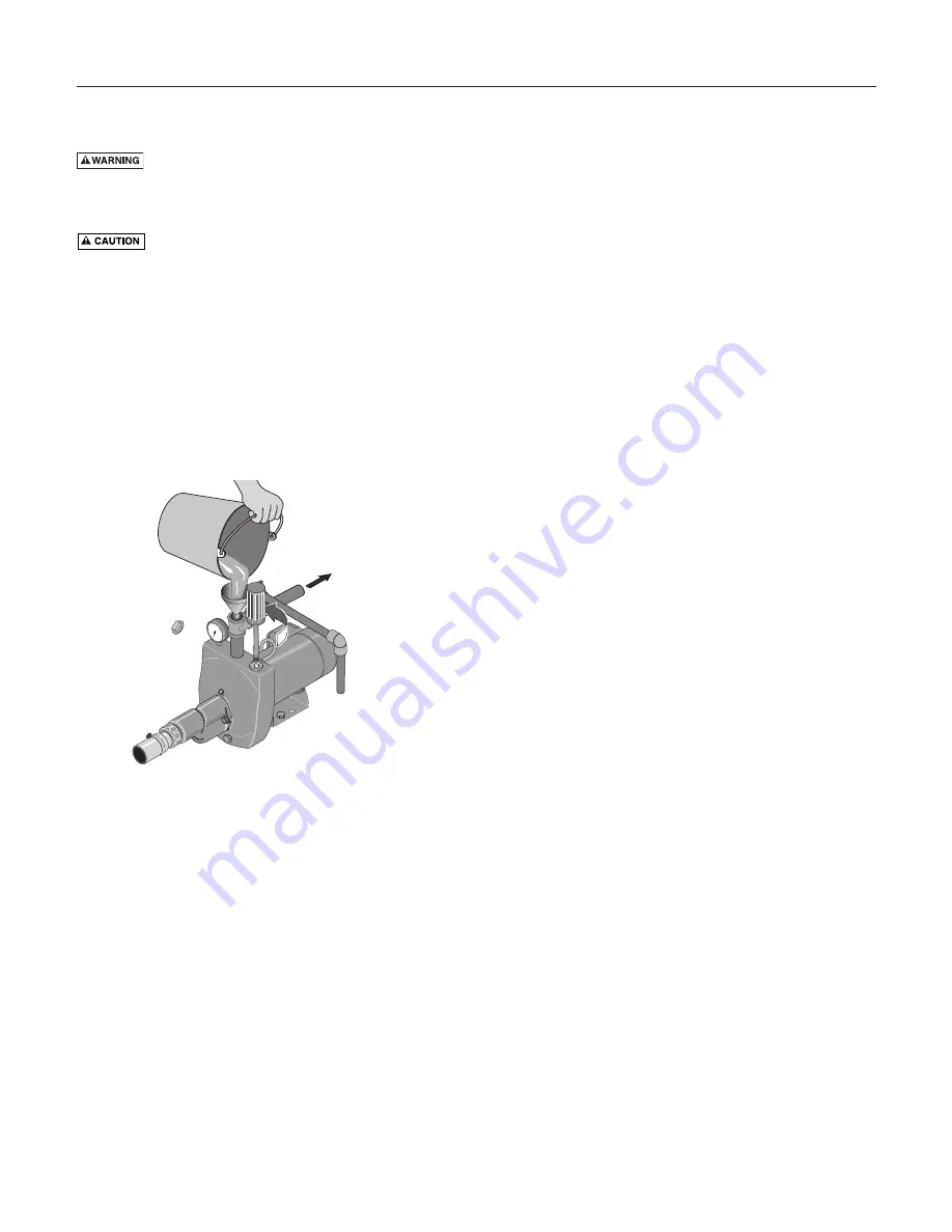
Step 1. Open the control valve as far as possible (see

Figure 15). Then remove the priming plug from
the pump and fill the pump, fill all piping
between the pump and the well, and make sure
that all piping in the well is full. If you have also
installed a priming tee 

in the suction piping,

remove the plug from the tee and fill the suction
piping.

Step 2. Replace all fill plugs. Leave the control valve

open (in a shallow well installation, the control
valve always stays open).

Step 3. Power on! Start the pump. The pump should

pump water in two or three minutes.

Step 4. If you don’t have water after 2 or 3 minutes, stop

the pump and remove the fill plugs. Refill the
pump and piping. You may have to repeat this
two or three times in order to get all the trapped
air out of the piping. The control valve remains
open throughout this procedure.

Step 5. After the pump has built up pressure in the sys-

tem and shut off, check the pressure switch oper-
ation by opening a faucet or two and running
enough water out to bleed off pressure until the
pump starts. The pump should start when pres-
sure drops to 30 PSI and stop when pressure
reaches 50 PSI. Run the pump through one or
two complete cycles to verify correct operation.
This will also help clean the system of dirt and
scale dislodged during installation.

Open control 

v

al

v

e

as far as possi

b

le

and fill p

u

mp and

piping thro

u

gh

priming port
or priming tee.

2411 0497

To Ho

u

sehold

W

ater System

60

0

1

0

0

2

Figure 15: Open Control Valve

Содержание HL Series

Страница 1: ...1 262 728 5551 English Pages 2 12 Installation Fonctionnement Pièces Pour plus de renseignements concernant l utilisation l installation ou l entretien Composer le 1 262 728 5551 Français Pages 13 23 Instalación Operación Piezas Para mayor información sobre el funcionamiento instalación o mantenimiento de la bomba Llame al 1 262 728 5551 Español Paginas 24 34 20 40 60 80 100 S416 Rev 4 23 09 293 W...

Страница 2: ...touch an operating motor Modern motors are designed to operate at high temperatures To avoid burns when servicing pump allow it to cool for 20 minutes after shut down before handling Do not allow pump or any system component to freeze To do so will void warranty Pump water only with this pump Periodically inspect pump and system components Wear safety glasses at all times when working on pumps Kee...

Страница 3: ...gle phase power through a phase converter will void the warranty Note also that three phase motors must be protected by three leg ambient compensated extra quick trip overload relays of the recommended size or the warranty is void Your only remedy and STA RITE s only duty is that STA RITE repair or replace defective products at STA RITE s choice You must pay all labor and shipping charges associat...

Страница 4: ...097 0497 20 0 60 8 1 0 Priming Tee and Plug Drive Coupling Drive Point Check Valve Drive point below water level Pressure Gauge Priming Tee and Plug Well Casing Foot Valve Sanitary Well Seal Suction Pipe From Well Foot Valve Screen 10 Min 5 10 Cased Well Open Water Strainer 1836 0695 Figure 5 Typical Shallow Well Installations To Household Water System Pressure Switch Suction Pipe From Well Air Vo...

Страница 5: ...h a standard tank must be capable of passing the entire pump capacity at 75 PSI pressure Connect the Air Volume Control AVC tube to the 1 8 NPT AVC port on the pump body Run the tubing from the pump s AVC port to the AVC mounted on the tank See the instructions provided with tank and AVC for details Sealing Pipe Joints Use only Teflon tape or Teflon based joint com pounds for making all threaded c...

Страница 6: ...the two outer screws on the pressure switch as shown in Figure 10 4 Attach the ground wire to the grounding connections as shown in Figure 10 5 If there are other wires they should be capped 6 Reinstall the Motor end cover Disconnect power before working on pump motor pressure switch or wiring NOTE 1 2 HP motors are wired for 115 volts only and have no motor wiring to change 3 4 HP or 1 HP motor t...

Страница 7: ...ween the pressure switch and the motor for motor grounding protection If the pressure switch is not connected to the motor connect the green ground screw in the switch to the green ground screw under the motor end cover Use a solid copper wire at least as large as the power supply wires Step 3 Connect the ground wire to a grounded lead in a service panel to a metal underground water pipe to a meta...

Страница 8: ... valve see Figure 14 and let the pressure drop until the pressure gauge needle starts to flutter When the needle flutters close the valve just enough to stop the flutter see Figure 14 Your pump is now operating at its most efficient point Step 6 After the pump has built up pressure in the sys tem and shut off check the pressure switch oper ation by opening a faucet or two and running enough water ...

Страница 9: ...control valve always stays open Step 3 Power on Start the pump The pump should pump water in two or three minutes Step 4 If you don t have water after 2 or 3 minutes stop the pump and remove the fill plugs Refill the pump and piping You may have to repeat this two or three times in order to get all the trapped air out of the piping The control valve remains open throughout this procedure Step 5 Af...

Страница 10: ...P U11 217P 10 Pressure Gauge 1 U239 2 U239 2 11 Control Valve Assembly 1 L262 5PS L262 5PS L262 5PS L262 5PS 12 Pump Body 1 L76 49 L76 49 L76 49 L76 49 13 Pipe Plug 1 U78 56ZPS U78 56ZPS U78 56ZPS U78 56ZPS 14 Drain Plug 1 U78 941ZPV U78 941ZPV U78 941ZPV U78 941ZPV 15 Base 1 J104 9C J104 9C J104 9C J104 9C 15A Motor Pad 1 C35 5 C35 5 C35 5 C35 5 16 3 8 16x1 1 2 Capscrew 2 U30 76ZP U30 76ZP U30 76...

Страница 11: ... Gauge 1 U239 2 11 Control Valve Assembly 1 01322 01322 01322 12 Pump Body 1 L76 48 L76 48 L76 48 13 Pipe Plug 1 U78 56ZPS U78 56ZPS U78 56ZPS 14 Drain Plug 1 U78 941ZPV U78 941ZPV U78 941ZPV 15 Base 1 J104 9C J104 9C J104 9C 15A Motor Pad 1 C35 5 C35 5 C35 5 16 3 8 16x1 1 4 Capscrew 4 U30 75ZP U30 75ZP U30 75ZP 17 Switch Tube 1 U37 672P U37 672P U37 672P 18 Quick Connect Elbow 1 U11 218P U11 218P...

Страница 12: ...a shallow well pump installed on a well with more than 25 ft depth to water in this case a deep well jet pump is needed D Pump does not deliver water to full capacity D Possible causes are the well water level is lower than estimated making a different nozzle venturi combination necessary steel piping if used is corroded or limed restricting capacity and increasing friction or the piping is too sm...

Страница 13: ...que l on intervien dra sur la pompe la laisser refroidir pendant 20 minutes après l avoir arrêtée avant de la toucher Ne pas laisser geler la pompe ni aucun autre élément du sys tème sinon la garantie sera annulée Ne pomper que de l eau avec cette pompe Périodiquement inspecter la pompe et tous les éléments du système Toujours porter des lunettes de sécurité lorsque l on intervient sur une pompe G...

Страница 14: ...ar l intermédi aire d un déphaseur Il faut également noter que les moteurs triphasés doivent être protégés par un relais de surcharge tripolaire thermocompensé à déclenchement extrêmement rapide du calibre recommandé sinon la garantie sera nulle et non avenue Le seul recours de l Acheteur et la seule responsabilité de STA RITE consistent à réparer ou à remplacer au choix de STA RITE les produits q...

Страница 15: ...refoulée dans le tuyau d aspiration puis aspirée par la pompe Vers le système d eau de la maison Contrôleur d air Tube du contrôleur d air Té d amorçage et bouchon Soupape de sûreté Manocontacteur Réservoir standard Tuyau d aspiration provenant du puits Tuyau d eau motrice vers le puits Deux tuyaux Un seul tuyau puits de 4 po de dia puits de 2 et plus grand et 3 po Tuyau d aspiration le plus gros ...

Страница 16: ...ilisée avec un réservoir standard doit pouvoir laisser passer tout le débit de la pompe à une pression de 75 lb po2 Brancher le tube du contrôleur d air sur l orifice de 1 8 de pouce NPT pratiqué dans le corps de la pompe Amener le tube de l orifice du contrôleur d air de la pompe jusqu au con trôleur d air monté sur le réservoir Pour plus de détails se reporter aux instructions fournies avec le r...

Страница 17: ...re figure 10 5 S il y a d autres fils leurs bouts doivent être isolés 6 Reposer le couvercle d extrémité du moteur Débrancher le courant électrique avant d intervenir sur la pompe le moteur le manostat ou le câblage REMARQUE Les moteurs de 1 2 ch sont câblés pour fonctionner sur un courant de 115 volts seulement il ne faut donc changer aucun câble Les plaquettes de connexions des moteurs de 3 4 ch...

Страница 18: ... gros que le diamètre des fils de tension 2 Il doit y avoir un raccordement en métal solide entre le manostat et le moteur pour une protection à la terre du moteur Si le manostat n est pas branché sur le moteur brancher la vis verte de mise à la terre du manostat sur la vis verte de mise à la terre qui se trouve sous le couvercle du moteur Utiliser un fil de cuivre massif ayant un diamètre au moin...

Страница 19: ...Figure 14 et laisser chuter la pression jusqu à ce que l aiguille du manomètre commence à osciller Pendant que l aiguille oscille fermer suffisamment la vanne de réglage pour arrêter l aiguille d osciller voir la Figure 14 La pompe fonctionne maintenant à son point le plus efficace 6 Après que la pression se sera accumulée dans le système et que la pompe se sera arrêtée vérifier le fonctionnement ...

Страница 20: ...e réglage reste toujours ouverte 3 Établir le contact Démarrer la pompe La pompe doit pomper l eau dans les deux ou trois minutes qui suivent 4 Si la pompe ne pompe pas d eau dans les 2 ou 3 minutes qui suivent l arrêter et déposer les bouchons de remplis sage Faire le plein de la pompe et des tuyauteries Il fau dra peut être répéter cette opération deux ou trois fois de façon à chasser tout l air...

Страница 21: ...omètre 1 U239 2 U239 2 11 Vanne de réglage 1 L262 5PS L262 5PS L262 5PS L262 5PS 12 Corps de la pompe 1 L76 49 L76 49 L76 49 L76 49 13 Bouchon fileté 1 U78 56ZPS U78 56ZPS U78 56ZPS U78 56ZPS 14 Bouchon de vidange 1 U78 941ZPV U78 941ZPV U78 941ZPV U78 941ZPV 15 Socle 1 J104 9C J104 9C J104 9C J104 9C 15A Support en caoutchouc 1 C35 5 C35 5 C35 5 C35 5 16 Vis à tête de 3 8 16x1 1 2 po 2 U30 76ZP U...

Страница 22: ...mètre 1 U239 2 11 Vanne de réglage 1 01322 01322 01322 12 Corps de la pompe 1 L76 48 L76 48 L76 48 13 Bouchon fileté 1 U78 56ZPS U78 56ZPS U78 56ZPS 14 Bouchon de vidange 1 U78 941ZPV U78 941ZPV U78 941ZPV 15 Socle 1 J104 9C J104 9C J104 9C 15A Support en caoutchouc 1 C35 5 C35 5 C35 5 16 Vis à tête de 3 8 16x1 1 4 po 4 U30 75ZP U30 75ZP U30 75ZP 17 Tube de manocontacteur 1 U37 672P U37 672P U37 6...

Страница 23: ...uses Prises d air dans la conduite d aspira tion baisse de niveau d eau dans le puits clapet de pied grippé ou bouché éjecteur bouché impulseur bouché clapet de pied ou crépine enfoui dans la boue au fond du puits et pompe pour puits peu profond posée dans un puits dont la profondeur est supérieure à 25 mètres jusqu à l eau dans ce cas une pompe à éjecteur pour puits profond est requise D Causes p...

Страница 24: ... evitar quemaduras al realizar el servicio a una bomba déjela enfriar por 20 minutos después de apagarla No permita que la bomba o cualquier componente del sis tema se congele Hacerlo invalidará la garantía Utilice esta bomba sólo para agua Inspeccione la bomba y los componentes del sistema per iódicamente Utilice gafas de seguridad durante todo el tiempo mientras trabaje en la bomba El área de tr...

Страница 25: ...uente de alimentación monofásica a través de un convertidor de fase Es importante indicador que los motores trifásicos deben estar protegidos por relés de sobrecarga de disparo extra rápido con compensación ambiental de tres etapas del tamaño recomendado de lo contrario la garantía quedará anulada Su único recurso y la única obligación de STA RITE es que STA RITE repare o reemplace los productos d...

Страница 26: ...gua a través de la Tubería de Succión Al Sistema Doméstico de Agua Control de Volumen de Aire Tubo de Control de Volumen de Aire T y Tapón para Cebar Válvula de Alivio Interruptor de Presión Tanque estándar Tubería de succión del pozo Tubería de transmisión al pozo Tubería doble Tubería simple diámetro del pozo diámetro del pozo 4 mínimo 2 y 3 Tubería de succión del pozo más grande Tubería de tran...

Страница 27: ... debe poder hacer pasar toda la capacidad de la bomba a una presión de 75 PSI Conecte el tubo de control de volumen de aire CVA al orificio de CVA de 1 8 NPT situado en el cuerpo de la bomba Extienda la tubería desde ese orificio hasta el control de volumen de aire montado en el tanque Para más información vea las instruc ciones suministradas con el tanque y el CVA antedichos Sellado de Juntas de ...

Страница 28: ...stra en el Figura 10 4 Conecte el cable a tierra a una de las conexiones a tierra según se ilustra en la Figura 10 5 Si hay otros cables tápelos 6 Vuelva a instalar la cubierta del motor Desconecte la corriente antes de trabajar en la bomba el motor el conmutador a presión o los cables NOTA Los motores de 1 2 HP vienen cableados sólo para 115 voltios y no tienen cables que se puedan cambiar Los ta...

Страница 29: ... haber una conexión metálica sólida entre el conmutador a presión y el motor para brindar protec ción a tierra para el motor Si el conmutador a presión no está conectado al motor conecte el tornillo de puesta a tierra verde en el conmutador al tornillo de puesta a tierra verde debajo de la tapa de extremo del motor Use un alambre de cobre sólido que sea por lo menos tan grande como los alambres de...

Страница 30: ...ón comience a oscilar vea la Figura 14 Ahora su bomba está operando en su punto más eficiente Paso 6 Después de que la bomba ha producido presión en el sistema y esté apagada verifique la operación del interruptor de presión abriendo una llave o dos y dejando correr suficiente agua para descargar la pre sión hasta que la bomba arranque La bomba debe arrancar cuando la presión caiga a 30 PSI y se d...

Страница 31: ...a La bomba debe bombear agua después de 2 ó 3 minutos Paso 4 Si no tiene agua después de 2 ó 3 minutos pare la bomba y retire todos los tapones de llenado Vuelva a llenar la bomba y la tubería Posiblemente tendrá que repetir esto dos o tres veces para sacar todo el aire atrapado en la tubería La válvula de control se debe mantener abierta durante todo el procedimiento Paso 5 Después de que la bomb...

Страница 32: ...217P 10 Medidor de presión 1 U239 2 U239 2 11 Válvula de control 1 L262 5PS L262 5PS L262 5PS L262 5PS 12 Cuerpo de la bomba 1 L76 49 L76 49 L76 49 L76 49 13 Tapón para tubería 1 U78 56ZPS U78 56ZPS U78 56ZPS U78 56ZPS 14 Tapón de drenaje 1 U78 941ZPV U78 941ZPV U78 941ZPV U78 941ZPV 15 Base 1 J104 9C J104 9C J104 9C J104 9C 15A Cojín de hule 1 C35 5 C35 5 C35 5 C35 5 16 Prisionero de 3 8 16x 1 1 ...

Страница 33: ...0 Medidor de presión 1 U239 2 11 Válvula de control 1 01322 01322 01322 12 Cuerpo de la bomba 1 L76 48 L76 48 L76 48 13 Tapón para tubería 1 U78 56ZPS U78 56ZPS U78 56ZPS 14 Tapón de drenaje 1 U78 941ZPV U78 941ZPV U78 941ZPV 15 Base 1 J104 9C J104 9C J104 9C 15A Cojín de hule 1 C35 5 C35 5 C35 5 16 Prisionero de 3 8 16x 1 1 4 4 U30 75ZP U30 75ZP U30 75ZP 17 Tubo del interruptor 1 U37 672P U37 672...

Страница 34: ...a de pie trabada o tapada eyector o impulsor tapado válvula de pie o filtro enlodado en el fondo del pozo una bomba para pozo de poca pro fundidad instalada en un pozo con más de 25 pies de profundidad de agua en estos casos se necesita una bomba Jet D Las causas posibles son el nivel del agua del pozo es inferior al estimado y se necesita hacer una combinación de venturi boquilla diferente la tub...

Страница 35: ...35 ...

Страница 36: ......

Отзывы: