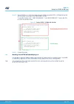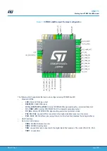
Figure 13.
STM32CubeMX project file pinout configuration
The following list of peripherals that can be re-configured using STM32CubeMX:
•
Standard GPIOs
–
LED
: status LED driving output
–
RS485_DE
: RS485 DE signal
–
OCTH_STBY1/OCTH_STBY2
: internal STSPIN32F0A signal setting the overcurrent threshold
–
OC_COMP_INT2
: internal STSPIN32F0A OC comparator secondary output
–
OC_SEL
: internal STSPIN32F0A signal setting overcurrent protection mode
–
PA0, PA1, PA2
: unused GPIOs connected to the digital Hall effect sensors of the motor
–
PA13, PA14
: SWD interface pins (using this pin for other functions disables the debug interface)
•
UART interface
•
Not motor control timers:
–
TIM14
: MODBUS timeout counter
–
TIM16
: MODBUS polling timer
–
TIM2
: unused timer also connected to the digital Hall effect sensors of the motor (PA0, PA1, PA2)
–
TIM17
: unused timer
UM2711
Starting from STM32CubeMX project
UM2711
-
Rev 1
page 12/18


