Step 5.
The automatically generated STM32CubeMX project miss some peripheral configurations. The
following changes must be done:
Step 5a.
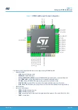
Reset configuration for PB0 (Reset_State option in drop-down list)
Step 5b.
Configure PF1 as GPIO_EXTI1 and label it “M1_ENCODER_Z”
Step 5c.
Configure PA15 as GPIO_Output and label it “RS485_DE”
Step 5d.
Configure PF0 as GPIO_Output and label it “LED”
Step 5e.
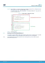
Configure the USART1 for asynchronous operation and map TX/RX to PB6/PB7 GPIOs. No
hardware flow control is required.
Details about configuration of the UART are shown in the following figures.
Figure 3.
UART configuration panel (basic)
Figure 4.
UART configuration panel (advanced)
Step 5f.
Configure one of the available timers as PWM no output for the MODBUS RTU timeout
management (by default TIM14).
It must be set in order to increment at a 50 μs rate (PSC = 2399 for 48 MHz clock).
UM2711
Starting from MotorControl Workbench project
UM2711
-
Rev 1
page 7/18


