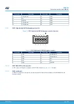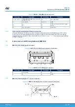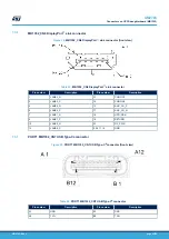
Pin number
Description
Pin number
Description
A3
TX1-
B3
TX2-
A4
V
BUS
B4
V
BUS
A5
CC1 (PA8)
B5
CC2 (PB15)
A6
D+
B6
D+
A7
D-
B7
D-
A8
SBU1
B8
SBU2
A9
V
BUS
B9
V
BUS
A10
RX2-
B10
RX1-
A11
RX2+
B11
RX1+
A12
GND
B12
GND
7.3.8
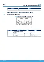
MB1352_CN8 and MB1352_CN9 daughterboard female connectors
MB1352_CN8 and MB1352_CN9 female connectors are used to implement the USB-C
®
daughterboard on
the mother board. MB1352_CN8 on the USB-C
®
daughterboard is connected to CN3 on the mother board,
and MB1352_CN9 on the USB-C
®
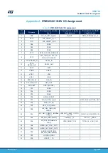
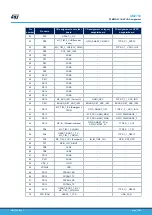
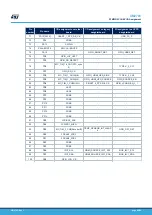
daughterboard is connected to CN2 on the mother board. Refer to
for a detailed signal definition of these connectors.
7.3.9
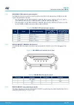
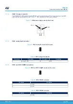
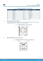
MB1352_CN10 USB 2.0 FS board to board connector
One female connector MB1352_CN10 is used to connect the mother board USB 2.0 FS data interface (DP/DM) to
USB Type-C
®
daughterboard connectors.
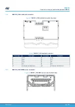
Table 45.
MB1352_CN10 USB 2.0 FS board to board connector
Pin
Signal
1
PA12
2
PA11
3
PA12
4
PA11
UM2783
Connectors on UCPD daughterboard (MB1352)
UM2783
-
Rev 1
page 43/59

