7.1.7
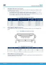
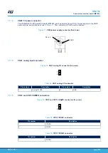
CN11 microSD
™
connector
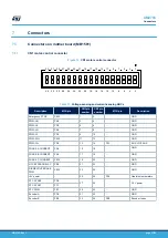
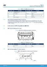
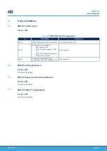
Figure 13.
CN11 microSD
™
connector (front view)
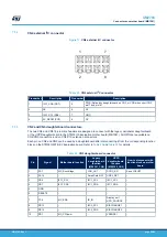
Table 27.
CN11 microSD
™
connector
Pin number
Description
Pin number
Description
1
NC
5
MicroSDcard_CLK (PB3)
2
MicroSDcard_CS (PD1)
6
Vss/GND
3
MicroSDcard_DIN(PA7)
7
MicroSDcard_DOUT(PB4)
4
+3V3
8
NC
-
-
10
MicroSDcard_detect (PC9)
7.1.8
CN9 and CN10 extension connectors
The two CN9 and CN10 22-pin male headers are designed to connect with daughterboard or standard wrapping
board to STM32G0C1E-EV Evaluation board. The standard width between CN9 pin1 and CN10 pin1 is 2700 mils
(68.58 mm). The standard is implemented on the majority of evaluation boards. Each pin on CN9 and CN10 can
be used by a daughterboard after disconnecting it from the corresponding function block on STM32G0C1E-EV
Evaluation board. Refer to
Table 28.
CN9 extension connector
Pin
Description
Alternative function
How to disconnect with function block on
STM32G0C1E-EV Evaluation board
1
PD13
FDCAN1_TX
Remove SB9
3
PD15
FDCAN2_TX
Remove SB11
5
PF8
-
-
7
PA13
T_JTMS / SWDIO / SWDAT
Remove SB13
9
PC9
SDCARD_DETECT
Remove SB42
11
PD5
LED1
Remove SB16
13
PD7
-
-
15
PF10
-
-
17
PF13
-
-
19
GND
-
-
UM2783
Connectors on mother board (MB1581)
UM2783
-
Rev 1
page 31/59

