


D
R
A
F
T
Hardware layout and configuration
UM1461
12/65
Doc ID 022138 Rev 1
2.7 CAN
STM3240G-EVAL evaluation board enables two channels of CAN2.0A/B compliant CAN
bus communication based on a 3.3V CAN transceiver on one DB9 connector (CN10). The
two CAN buses can be disconnected by jumpers from relevant STM32F407IGH6 I/Os which
are shared with FSMC and USB OTG HS. Jumpers JP3 and JP10 must be refit to enable
CAN1 or CAN2 as listed in
Table 5
.
High-speed, Standby and Slope Control modes are available and can be selected by setting
jumper JP7.
2.8
RS-232 and IrDA
Both RS-232 and IrDA communication is enabled by D-type, 9-pin RS-232 connectors
(CN16) and IrDA transceiver U11 which are connected to USART3 of STM32F407IGH6 on
STM3240G-EVAL evaluation board.
For ISP support, two signals are added on the RS-232 connector CN16:
●
Bootloader_RESET (shared with CTS signal)
●
Bootloader_BOOT0 (shared with DSR signal)
RS-232 or IrDA can be selected by setting of JP22 and ISP can be enabled by setting of
jumper JP29 and JP34.
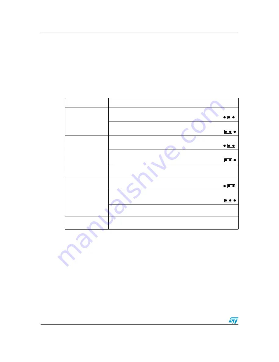
Table 5.
CAN-related jumpers
Jumper
Description
JP3
To connect CAN1_TX to CAN transceiver, set JP3 as shown:
To connect CAN2_TX to CAN transceiver, set JP3 as shown:
JP10
To connect CAN1_RX to CAN transceiver, set JP10 as shown:
To connect CAN2_RX to CAN transceiver, set JP10 as shown:
PD0 and PB5 are disconnected from the CAN transceiver and used for
FSMC and USB_OTG_HS when jumper JP10 is not fitted (default setting).
JP7
To enable the selected CAN transceiver to work in Standby mode,
set JP7 as shown:
To enable the selected CAN transceiver to work in High-speed
mode, set JP7 as shown (default setting):
To enable the selected CAN transceiver to work in Slope Control mode, do
not fit a jumper on JP7.
JP9
To enable the terminal resistor for the selected CAN, fit a jumper on JP9.
(Default setting: not fitted)
3
2
1
3
2
1
3
2
1
3
2
1
3
2
1
3
2
1
All manuals and user guides at all-guides.com