3
Operation
The most common solution to limit the inrush current at startup is to use a serial impedance after the rectifier
bridge. To reduce the power loss, a mechanical relay bypasses the serial impedance as soon as the output DC
capacitor is charged and when the converter starts up.
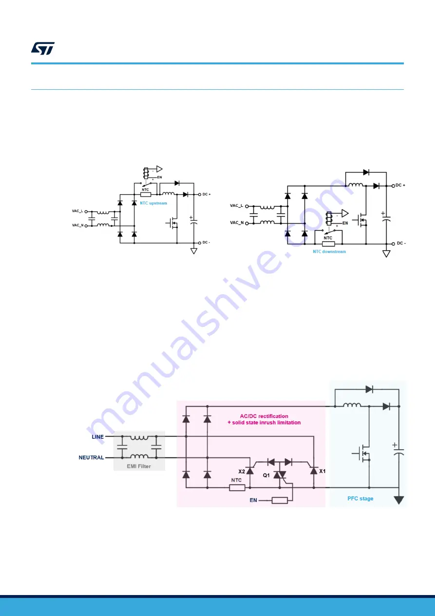
The figure below shows the typical schematic of a power converter using a bypass relay at the DC bus high side
(NTC upstream) and at the DC bus low side (NTC downstream).
Figure 5.
Typical schematic of a power converter using relay bypass
The bulkiness of the relay and its slow response has led to a new architecture based on a half-controlled rectifier
bridge.
The
board allows replacing the relay with two SCRs triggered by Q1 (
, SOT223
package, four-quadrant triac), offering high reliability, long service lifetime, electromagnetic interference reduction
and a faster response to line dips. Moreover, this bypass solid-state solution has no moving parts, preventing from
spark and contact arcing that are the root cause of the reduction of the electromechanical relay lifetime.
Solid-state topologies with SCRs allow applications to comply easily with the following standards:
•
IEC61000-3-3 (voltage fluctuations and flicker in public low-voltage supply systems, for equipment with rated
current ≤ 16 A);
•
IEC61000-4-11 (voltage dips, short interruptions, and immunity tests for voltage variations).
Figure 6.
Schematic of the STEVAL-SCR002V1 connected to PFC
3.1
Startup
At system power-up, the EN signal is disabled and no gate current is applied to the Q1 gate terminal. Then, the
triac remains off and no current can flow through the SCR gates. As a result, SCRs X1 and X2 are in the off state.
The inrush current flows through the bridge diodes of the font-end rectifier, limited by the inrush power resistor
(NTC or PTC) as shown below.
UM2948
Operation
UM2948
-
Rev 1
page 6/28


