background image

Page 15 

Afton Bay Installations Manual 


COMBUSTION AIR 


WARNING: USE THE AIR INTAKE DAMPER FOR ADJUSTING COMBUSTION INLET 

AIR ONLY! OTHER METHODS OF RESTRICTING OR BLOCKING COMBUSTION 

INLET AIR ARE STRICTLY PROHIBITED! 


Figure 11 

Stove Air Inlet Connection 


1.


It is recommended that the stove be connected to an outside source of combustion air under 
certain  conditions  (negative  pressure).  An  outside  air  kit  is  available,  part  #  100354  or  any 
flexible metal hose or rigid metal pipe (conduit) must be connected around (NOT INSIDE) 
the  combustion  air  inlet  tube  (Figure  11A).  Be  careful  not  to  pinch  or  bend  the  outside  air 
pipe with too small a radius. Outside Air Pipe may be terminated flush with the outside wall 
but should be protected from wind and weather by a hood. Note: The outside air pipe must 
terminate above the maximum snow line and below the exhaust vent outlet. 

 
2.


Outside  air  may  be  drawn  from  a  semi-enclosed  attic  or  crawl  space  or  any  semi-enclosed 
space. Take care not to draw cold air past water pipes that may freeze.  

 
3.


Increase  the  outside  air  pipe  diameter  to  3”  for  runs  over  ten  (10)  feet  and  elevation  over 
4,000 feet. Note: Long runs should be avoided.  

 
4.


Terminate the outside air pipe below the exhaust vent outlet. 

 
5.


An open mesh screen should be placed over the outside air pipe opening to prevent birds or 
rodents from nesting in the opening. Use an elbow or shield to prevent prevailing winds from 
blowing directly into the outside air intake pipe.  NOTE: Mesh screen should be no smaller 
than one-fourth inch (1/4”) by one-fourth inch (1/4”).  

 
6.


In  the  case  of  a 

Custom  made

  sealed  fireplace  insert  shroud,  an  outside  air  inlet  to  the 

fireplace cavity is necessary to ensure adequate airflow for combustion.  

 
WARNING:  OUTSIDE  COMBUSTION  AIR  IS  REQUIRED  FOR  ALL  MOBILE  HOME 
INSTALLATIONS! 

Содержание AFTON BAY

Страница 1: ...ng Termination Requirements 12 13 Combustion Air 15 Electrical Connections 16 Floor Protection 17 Clearances to Combustible Materials 18 Mobile Home Installation 20 Thermostat Installation and Operation 22 Contact local building or fire officials about restrictions and installation inspection requirements in your area Please read this entire manual before installation and use of this pellet fuel b...

Страница 2: ...NY LOCAL INSTALLATION RESTRICTIONS AND INSPECTION REQUIREMENTS DEFINITION OF STOVE The word stove as used in this manual is interpreted to mean a pellet burning freestanding stove insert or zero clearance fireplace unless otherwise noted SAFETY TESTING The stove has been independently tested and listed by Warnock Hersey Laboratories in accordance with the proposed ASTM Standards and the applicable...

Страница 3: ...least 3 screws and correctly installed Follow vent manufacturer s instructions Seal all joints with high temperature silicone to create an airtight seal 3 Any plated areas should be cleaned thoroughly with a glass cleaner such as Windex and a soft cloth just before lighting the first fire This will remove fingerprints and oils that may cause a permanent stain or mark on the gold plating the first ...

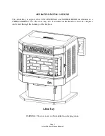
Страница 4: ...Bay is approved for CONVENTIONAL and MOBILE HOME installations as a FREESTANDING stove The stove may also be installed on the Hearth in front of a fireplace and vented through the chimney of the fireplace WARNING The stove must not be installed in a sleeping room Afton Bay ...

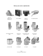
Страница 5: ...aVent Energy Vent LTD James A Ryder and Selkirk Metalbestos and is carried by many local pellet stove dealers In this manual approved venting will be referred to a PL vent or Single wall vent All single wall vent adaptors must be stainless steel NOTE TYPE B GAS VENT MUST NOT BE USED IN ANY PELLET STOVE INSTALLATION Examples of venting system components follow High temperature ceramic roping reduce...

Страница 6: ...YPICAL PL VENT COMPONENTS RAIN CAP VERTICAL OR WALL THIMBLE CHIMNEY SUPPORT BRACKET HORIZONTAL ADAPTER ADJUSTABLE LENGTH SINGLE TEE SINGLE REDUCTION DOUBLE TEE PIPE w TEE CAP TEE w TEE CAP w TEE CAP PIPE ADAPTER INCREASER 450 ELBOW 900 ELBOW ...

Страница 7: ...T CLEARANCES TO COMBUSTIBLES AS REQUIRED STRICTLY OBSERVE THE PL VENT MANUFACTURER S SAFETY SPECIFICATIONS QUANTITY OF MATERIALS 1 Installing the vent system with a minimum of three feet 3 of vertical rise above the stove exhaust port will provide some Natural Draft FAILURE TO PROVIDE THE NATURAL DRAFT THAT RESULTS FROM A VERTICAL RISE MAY RESULT IN SMOKE BEING RELEASED INTO THE HOUSE WHEN ELECTRI...

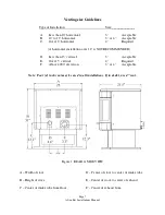
Страница 8: ... installation over 12 is NOT RECOMMENDED D Less than 15 vertical 3 Acceptable E Over 15 vertical 4 Required F Above 4000 elevation 3 or 4 Acceptable Note Four 4 inch vent may be used in all installations If in doubt use 4 vent Figure 1 REAR SIDE VIEW A Width of stove B Height of stove C Center of intake tube from floor D Center of stove to center of intake tube E Center of stove to center of exhau...

Страница 9: ...ee elbow I PL Vent Fire Stop B Thimble J Roof Flashing C PL Vent Section K Storm Collar D Stove Exhaust Pipe L Rain Cap E Air Intake Damper M Outside Air Pipe F Air Vent Damper N PL Vent Section G 90 degree elbow O Wall Band H 45 degree elbow P Outside Air Inlet Cover 1 PL vent may be installed directly through a combustible wall ceiling or roof according to PL vent manufacturer s instructions See...

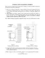
Страница 10: ...When terminating the exhaust system under the house eaves Figure 4 the end of the vent pipe system must be at least twelve inches 12 from the wall and 24 below the eave a 90 degree G and a 45 degree elbow may be used H 2 When extending through the roof Figure 5 install a PL vent fire stop I in the ceiling or in the eaves if the eaves are boxed in Install roof flashing J and a storm collar K Extend...

Страница 11: ...ap that reduces the outlet of the chimney to the size of the liner is required Extend the exhaust vent above the chimney chase cap and finish it off with a rain cap A single wall liner may need to be insulated to maintain adequate exhaust temperatures in the vent system Note Outside Chimneys frequently are difficult to keep warm if in doubt insulate the liner Figure 6 Figure 7 Venting into Masonry...

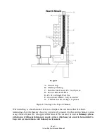
Страница 12: ...onal Figure 8 Venting to the Top of Chimney When installing as a hearth mount stove into a fireplace the unit must either be relined terminating above the chimney chase top or positively connected to the existing chimney system using a block off plate D An approved flex liner of PL vent must be used A chimney system with known drafting problems may require a liner which may also need to be insulat...

Страница 13: ...ports garage attic crawl space etc or any location that can build up a concentration of fumes 3 Vent surfaces can get hot enough to cause burns if touched by children Non combustible shielding or guards may be required The type of installation must first be considered before determining the exact location of the venting termination in relation ship to doors window cavities or air vents See figures...

Страница 14: ...from the outside atmosphere and all flue gases are discharged to the outside atmosphere Special Venting Arrangements are listed in NFPA 211 31 10 7 1 2 The Vent Terminal of a Direct Vent Appliance with an input of 10000 BTU Hr or less shall be located at least 6 from any opening into a building and such an appliance with an input of over 10000 BTU Hr but not over 50000 BTU Hr shall not be located ...

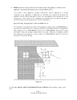
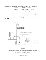
Страница 15: ...point 3 915mm FROM a gas meter regulator assembly 2 610 mm FROM any adjacent combustibles such as Adjacent buildings fences protruding parts of the structure roof eaves or overhangs plants shrubs etc Note Certain local code restrictions may apply Check with Local Officials first before installing FIGURE 10 VENTING TERMINATION CLEARANCE REQUIREMENTS SIDE VIEW All dimensions show MINIMUM distances ...

Страница 16: ...rminate above the maximum snow line and below the exhaust vent outlet 2 Outside air may be drawn from a semi enclosed attic or crawl space or any semi enclosed space Take care not to draw cold air past water pipes that may freeze 3 Increase the outside air pipe diameter to 3 for runs over ten 10 feet and elevation over 4 000 feet Note Long runs should be avoided 4 Terminate the outside air pipe be...

Страница 17: ...mately 3 amps 5 amps with igniter running 2 The power cord must be carefully routed to avoid contact with any hot or sharp exterior surface areas of the stove Figure 11B Any stove installed in a mobile home must be electrically grounded to the steel chassis of the home and bolted to the floor in Model compliance with and according to building code requirements 3 In Canada the electrical installati...

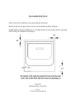
Страница 18: ...d on a non combustible protective pad Hearth models may be placed directly on the noncombustible hearth of a fireplace The Hearth must extend a minimum of 6 152 mm in Front of Unit and beyond each side of the Fuel Loading and Ash Removal Opening s Figure 12 Floor protection Top View ...

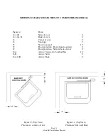
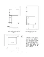
Страница 19: ...A B Back of stove 4 13 Corner of stove 4 13 Vent pipe 3 15 Stove to mantel 12 15 Floor protection Front from faceplate 6 12 Floor protection Sides back of stove 0 16A Alcove Vertical to Combustibles 16 16B Alcove Sides 4 16A 16B Alcove Back 4 Figure 13 Top View Figure 14 Top View Clearances corners of stove Clearances Sides and Back ...

Страница 20: ...Installation Top View Figure 16B Although 4 is the minimum clearance to the sides of the stove this is not recommended due to the need for access into the inside of the stove for the maintenance as spelled out in the Operations Manual Please read the section covering Daily Periodic and Yearly Maintenance in the Operations Manual ...

Страница 21: ...ddition to all previously detailed requirements mobile home installations must observe the following Figure 17 1 WARNING DO NOT INSTALL IN A SLEEPING ROOM 2 WARNING COMBUSTION AIR MUST COME FROM THE OUTSIDE OF THE MOBILE HOME FAILURE TO DO SO MAY CREATE NEGATIVE PRESSURE WITHIN THE MOBILE HOME AND COULD DISRUPT PROPER VENTING AND OPERATION OF THE PELLET STOVE 3 CAUTION THE STRUCTURAL INTEGRITY OF ...

Страница 22: ...at location where PL vent exits the structure 7 Check any other local building codes or other codes that may apply 8 Do no use components other than those specified for use with this unit Refer to pages 4 5 6 and 7 9 Floor protection requirement must be followed precisely 10 PL Vent must be used for exhaust venting Single wall vent is not allowed Follow PL Vent manufacturer s installation directio...

Страница 23: ...en the T Stat Mode and the SmartStat Mode We recommend using the Fully Automatic SmartStat Mode 1 Once you have successfully lit your stove set the thermostat to your desired heating needs 2 Set the HEAT ADJUST selector to a position that will effectively create a rise in room temperature above your thermostat setting The recommended heat adjust settings while using a thermostat are any position b...

Страница 24: ...Page 23 Afton Bay Installations Manual Notes Serial Number Date of Purchase Dealer Information Even Temp Inc P O Box 127 Waco NE 68460 EMAIL support stcroixstoves com WEB ADDRESS stcroixstoves com ...

Отзывы: