background image

4

Application

The flush-mount mounting frame
accessory ZUR 611-... is used to-
gether with the flush-mount housing
end pieces GE 611-0 and the appro-
priate flush-mount housing adaptor,
GZ 611-1, GZ 611-2  or GZ 611-3,
to convert system telephones of line
6.. and of line 7... from wall mount
to flush mount models. These
components are also required when
the telephones are combined with
monitors or when the T 611-... is
also used with multifunctional
module(s) MFM 611-10 as a flush-
mount model.
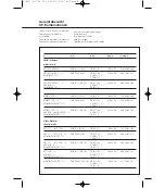
The following tables indicate which
flush-mount mounting frames with
flush-mount housings and their
dimensions are required for which
combinations.

Installation
1 Table of flush-mount
combinations
*

=  Equipment comb. 

**

=  Access. flush-mount 
frame   

***

=  Access. flush-mount 
housing

****

= Size of cut- out frame for 
Hollow-wall fastener 
(B X H mm)

*****

= Dimension (B x H x T mm)

Installation with flush-mount
housing

Assemble the required flush-mount
housing configuration, break out the
cable knockout and plaster in the
housing.

Attention

2

Do not remove the injected plaster

protector.

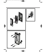
A Installing the system telephone

3

Fasten the proviced end pieces to

the ZUR 611-... using the counter-
sunk head screws.

4

(Not shown) 

Remove the injected plaster protec-
tor of the flush-mount housing with
a knife.

5

Use the provided notched dia.  

3.5 x 25 mm screws to fasten flush-

mount mounting frame ZUR 611-...
in the flush-mount housing. Snap
the ABS cover strips supplied on the
top and bottom of the flush-mount
mounting frame as shown. 

6

Remove the upper half of the

housing of system telephone.

7

Pull the connecting leads through

the cable knockout in the lower half
of the housing and use the supplied
notched screws dia. 3.9 x 10 mm to
fasten to the lower half of the
housing in the flush-mount mount-
ing frame ZUR 611-....

8

(Not shown) 

Connect the system telephone as
per corresponding wiring diagram.

9

(Not shown) 

Put the upper half of the housing
back in place.

B Installing, for example, the 
HT/T MO combination

Carry out steps 1 to 5 as described
above.

10

Open system telephone and

monitor as shown.

11

Break out the knockout links "a"

in the system telephone and lower
half of the monitor. Use the 2 con-
necting elements accompanying the
monitor to screw down the lower
halves. 

12

Pull the connecting leads through

the cable opening in the lower
halves of the housing and fasten the
lower halves of the housing in flush-
mount mounting frame ZUR 611-...
with the provided notched screws
dia. 3.9 x 10 mm.

13

(Not shown) 

Connect the equip-ment as per
corresponding wiring diagram. Use
the 7-pole cable accompanying the
monitor for the connections
between HT/T 611-..., HTA/HTS/
HTC 711-... / BTS/BTC 750-... and
MOM/ MOC/MOCT 711-... 

14

(Not shown) 

Put the upper half of the housing
back in place.

Follow the procedure above for
combinations with other equipment
configurations.

Multi-functional modules 
MFM 611-10 are always mounted in
a row to the right of the system
telephone T 611-... first; the monitor
follows. 
No more than 3 MFM 611-10
modules are to be mounted in a row
with system telephone T 611-...

C Installation with hollow-wall
fastener accessory

A hollow-wall fastener accessory 
ZHB 611-0 consists of 2 pairs of
retaining clips and screws.

15

Install an appropriate number of

retaining clips in the flush- mounting
frame accessory as shown, according
to the size of the flush-mount
housing.

a

Fit the supports on to the reverse

side 

b

Push the screw through the

appropriate hole in the mounting
frame and at the same time screw in
the retaining clip and the support

16

Fasten the proviced end pieces to

the ZUR 611-... using the counter-
sunk head screws

17

(Not shown) 

Install the flush-mount mounting
frame accessory in the hollow wall.

18

(Not shown)

Snap the supplied ABS cover strips
on top and bottom of the flush-
mount moun-ting frame. 

19

(Not shown)  

Install system telephones or com-
binations as described under A 6 to
9 or B 10 to 14, respectively.

English

Installation

ZUR611_212720  22.05.2002  13:16 Uhr  Seite 4

Содержание GZ 611-1

Страница 1: ... 0 et GZ 611 1 2 3 Accessorio da incasso ZUR 611 con GE 611 0 e GZ 611 1 2 3 Inbouw montageraam montage ZUR 611 met GE 611 0 en GZ 611 1 2 3 Tilbehør til planforsænket ZUR 611 med GE 611 0 og GZ 611 1 2 3 Tillbehör för infällt mon tage ZUR 611 med GE 611 0 och GZ 611 1 2 3 Příslušenství pro montáž pod omítku ZUR 611 s GE 611 0 a GZ 611 1 2 3 ZUR611_212720 22 05 2002 13 16 Uhr Seite 1 ...

Страница 2: ...tallic HTC 711 BTC 750 ZUR 611 01 SM GE 611 0 98 x 254 123 x 268 x 46 HTC 711 BTC 750 ZUR 3000 3 SM GE 611 0 276 x 254 300 x 268 x 51 MOM MOC MOCT 711 2 GZ 611 1 2 GZ 611 3 HTC 711 BTC 750 ZUR 611 10 3 SM GE 611 0 342 x 254 364 x 268 x 46 VBE 650 2 GZ 611 1 MOM MOC MOCT 711 GZ 611 2 BTC 750 ZUR 611 10 3 SM GE 611 0 342 x 254 364 x 268 x 51 BVE 650 2 GZ 611 1 MOM MOC MOCT 711 GZ 611 2 MOM MOC MOCT ...

Страница 3: ...3 2 3 16 5 6 ZUR611_212720 22 05 2002 13 16 Uhr Seite 3 ...

Страница 4: ...2 7 12 15 11 ZUR611_212720 22 05 2002 13 16 Uhr Seite 2 ...

Страница 5: ...9 Ohne Abbildung Gehäuse Oberteil wieder anbringen B Einsetzen z B der HT T MO Kombination Vorgehensweise wie unter Punkt 1 5 vorher beschrieben 10 Systemtelefon und Monitor wie dargestellt öffnen 11 Vorgeprägte Verbindungsstege a im Systemtelefon und Monitor Unterteil ausbrechen und Unterteile mit den dem Monitor beiliegenden 2 Verbindungselementen verschrau ben 12 Anschlussdrähte durch Kabelein ...

Страница 6: ...er half of the housing back in place B Installing for example the HT T MO combination Carry out steps 1 to 5 as described above 10 Open system telephone and monitor as shown 11 Break out the knockout links a in the system telephone and lower half of the monitor Use the 2 con necting elements accompanying the monitor to screw down the lower halves 12 Pull the connecting leads through the cable open...

Страница 7: ... Remettez le boîtier supérieur en place B Montage de la combinaison HT T MO exemple Procédez comme décrit sous les points 1 à 5 ci dessus 10 Ouvrez le téléphone système et le moniteur comme illustré par le schéma 11 Cassez les entretoises de liaison a pré estampées dans le téléphone système et dans la partie inférieure du moniteur et vissez les boîtiers inférieurs avec les deux éléments de liaison...

Страница 8: ...periore della scatola B Inserimento della combina zione HT T MO per es Procedere come descritto ai punti 1 5 10 Aprire come raffigurato il siste ma citofonicoe il monitor 11 Aprire rompendole le piattine di collegamento a prestampate del sistema citofonico e della parte infe riore del monitor e collegare a vite le parti inferiori con i due elementi di collegamento in dotazione con il monitor 12 In...

Страница 9: ...an bijvoorbeeld de HT T MO combinatie Volg de stappen 1 5 zoals hier boven beschreven 10 Systeemtelefoon en monitor zoals getoond openen 11 Voorgestanste verbindingsdelen a in zowel het monitor als telefoon onderstuk verwijderen en de delen met de bij de monitor geleverde verbindingselementen samen bou wen 12 Bedrading door de kabelin voeren in de onderzijde van het toestel naar binnen trekken en ...

Страница 10: ...temtelefonens øvre del monteres igen B Montage af f eks HT T MO kombinationen Fremgangsmåde pkt 1 5 som beskrevet før 10 Systemtelefon og monitor åbnes som vist 11 Forprægede forbindelsesstykker a i systemtelefonens og monitor ens underdel trykkes ud Underde lene samles med forbindelsesele menterne med de skruer som følger med monitoren 12 Tilslutningsledninger føres gennem kabelindføringen og tel...

Страница 11: ...igen B Montering av t ex HT T MO kombinationen Utför montaget enligt punkt 1 5 10 Öppna systemtelefonen och monitorn enligt beskrivningen 11 Bryt upp de stansade skarvarna a i systemtelefonen och monitorns nedre halva och skruva fast de nedre halvorna med de två skarvdelarna till monitorn 12 För in kablarna genom kabelin föringen till de undre lådhalvorna och skruva fast dessa med bifogade spårskr...

Страница 12: ...lefon zapojit podle příslušného vnějšího schématu zapojení 9 Bez zobrazení Horní část krytu opět namontovat B Instalování např HT T MO kombinace Postup jako popsáno pod předchozímí body 1 5 10 Systémový telefon a monitor podle vyobrazení otevřít 11 Předražené spojovací trnože a v systémovém telefonu a dolní části monitoru vylomit a spodní části sešroubovat 2 spojovacími prvky dodanými s monitorem ...

Страница 13: ...11 ZUR611_212720 22 05 2002 13 16 Uhr Seite 11 ...

Страница 14: ...212720 S Siedle Söhne Telefon und Telegrafenwerke Stiftung Co Postfach 1155 D 78113 Furtwangen Bregstraße 1 D 78120 Furtwangen Telefon 49 0 7723 63 0 Telefax 49 0 7723 63 300 www siedle de info siedle de ZUR611_212720 22 05 2002 13 16 Uhr Seite 12 ...

Отзывы: