SPIDAR Software
50
and right using the arrows. The number of arrows on the left and right buttons, correspond to
the movement of the waveform. More arrows mean a larger (or coarser) movement of the
waveform in that direction. If your application dictates otherwise, adjust manually for more or
less time prior to recording data.
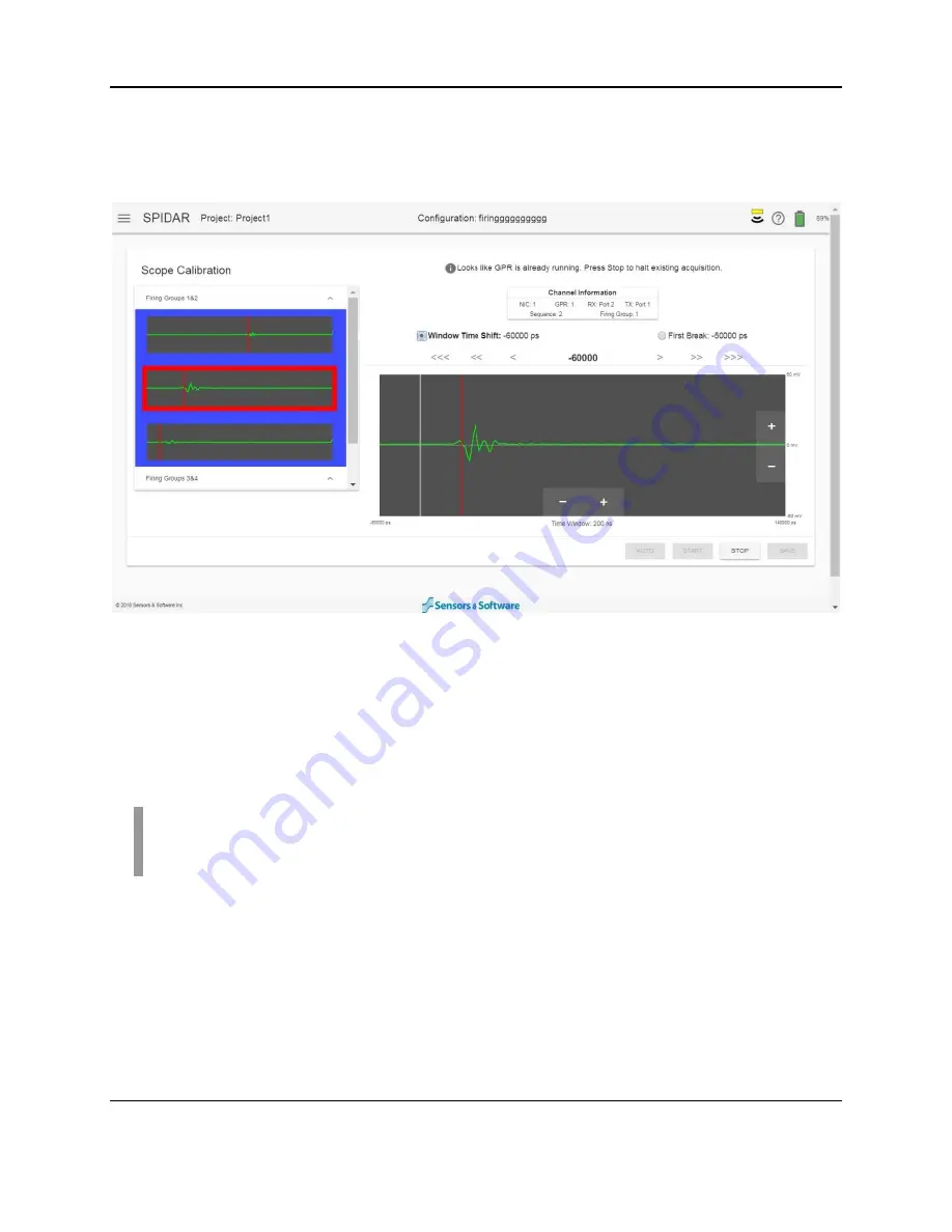
Figure 4-33: Manually setting Window Time Shift
Next, select the First Break option below the Channel Information box. Selecting the left and
right arrow buttons will move the red vertical line correspondingly. Position the start of the
waveform to line up with the red vertical line, near the 10% mark shown on the screen. The
correct placement of the waveform is shown in Figure 4-32.
Once complete, press
Stop
then
Save
to set these values in the NIC-500. Repeat for other
firing groups on this NIC-500, then repeat for other NIC-500s if present.
NOTE:
If the pulse cannot be found, and all connections are made, check the batteries in
the Low Frequency transmitter. If the batteries are OK, there could be a problem with the
transmitter.
Содержание SPIDAR NIC-500s
Страница 1: ......
Страница 2: ...ii...
Страница 4: ...Warranty Confirmation iv...
Страница 6: ...vi...
Страница 10: ...Introduction 2...
Страница 28: ...Getting Started 20...
Страница 66: ...SPIDAR Software 58...
Страница 78: ...SPIDAR SDK 70...
Страница 88: ...Compatibility 80...
Страница 90: ...Technical Specifications 82...
Страница 94: ...Appendix B Components 86 Item Item Code Noggin Cable 10m 100 52 0050 Noggin Cable 30m 100 52 0062...
Страница 102: ...Appendix D GPR Knowledge 94...
Страница 106: ...Appendix F Health Safety Certification 98...
Страница 114: ...Appendix G GPR Emissions Interference and Regulations 106...
Страница 116: ...Appendix H Instrument Interference 108...
Страница 118: ...Appendix I Safety around Explosive Devices 110...


