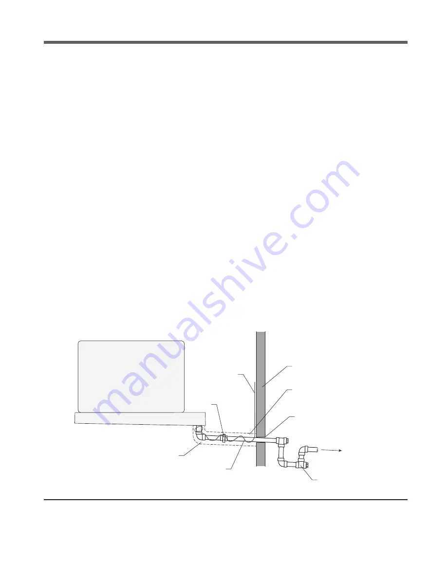
SPX SGS REFRIGERATION STC Series Скачать руководство пользователя страница 6

FIGURE 2 

Drain Line

installation

5 REFRIGERANT WARNING 

The use of any refrigerant can be dangerous under certain 
conditions. Where people or product can be exposed to hazardous 
conditions, daily inspections should be made for the detection 
of any defect or malfunction that could cause the escape of the 
refrigerant and cause harm. In the case of halocarbon refrigerants, 
electronic detection devices are available for sensing the presence 
of such refrigerants in the atmosphere. 

Ammonia

 is a “self-alarming” gas with its strong odor but detection 

devices are strongly recommended. People and product are a 
concern based on the concentration levels (ppm) of ammonia 
along with OSHA and EPA regulations. An ammonia gas detection 
device connected to an external alarm system to warn that a 
leak is occurring is recommended. Refer to local codes and Fire 
Department for additional local regulations. 

Only experienced, qualified personnel should install, operate, and 
maintain detection and alarm equipment.

6 PIPING INSTALLATION

6.1 DRAIN LINE 

The drain line should be connected to both drain pans, and should 
be as short and as steeply pitched as possible with a minimum 

of ¼” drop per running foot. The drain line should be the same 
size, or one size larger then drain pan connections. A drain line 
trap should be installed to prevent warm moist air from migrating 
through the drain line. The trap should be located in the warmest 
and/or lowest section of the piping to avoid freezing and provide 
sufficient liquid head for flow through the trap. If the temperature 
surrounding the drain line is below freezing (32°F) it must be 
wrapped with a drain line heater and insulation. Be sure to also wrap 
the drain pan coupling. The drain line heater should be energized 
continuously, but to avoid the possibility of overheating heat tape 
manufacturers recommend a thermostat be installed. Be sure to 
follow the manufacturer’s recommendations. The drain line trap 
should be outside of the freezing space. See Figure 2. 
A union at the drain pan connection is recommended for future 
servicing. The union should be located outside the edge of the 
drain pan so that when the pan is lowered for cleaning or repair the 
drain line run is not in the way. Use two wrenches when tightening 
to prevent the drain fitting from twisting and damaging the drain 
pan. See Figure 3. 
Long runs of drain line, i.e. more than a few feet, should be supported 
by hangers to avoid damage to the drain pan. For cleaning and 
inspecting the drain, tees with plugs are recommended instead 
of elbows. 

Insulated

Wall

Evaporator

Drain pan

Heating cable

power line

Drain line wrapped

with insulating material

Thermostatically controlled

heating cable

Union

Vapor seal the

pipe penetration

4" to 6"

drain trap

with access

Condensate

drain line

Slope drain pipe down

and away from evaporator

(1/4" per foot of pipe)

Содержание SGS REFRIGERATION STC Series

Страница 1: ...STC Series twin unit cooler INSTALLATION OPERATION MAINTENANCE E329630 ISSUED 02 2020 READ AND UNDERSTAND THIS MANUAL PRIOR TO OPERATING OR SERVICING THIS PRODUCT user manual SGS REFRIGERATION...

Страница 2: ...Interpiping 8 6 4 Evacuation and Leak Test 8 6 5 DXA And Suction Accumulators 8 7 Electrical 9 7 1Field Wiring 9 7 2Electrical Data 9 7 3Suggested No Defrost Requirement Sequence of Operation 17 7 4S...

Страница 3: ...ocate the expansion valve bulb on a horizontal length of suction line closer to the connection stub Position the bulb in a 3 4 8 or 9 o clock position Do not position the bulb on the top or the bottom...

Страница 4: ...ould be in place before the unit is hung See Sections 2 3 and 2 4 The unit must be level in all directions to insure proper drainage of the condensate drain pan FIGURE 1 Unit Dimension 15 75 5 25 LENG...

Страница 5: ...00 64 00 24 00 94 00 59 75 8 115 00 70 00 24 00 94 00 65 75 30 4 133 00 62 00 28 00 112 00 57 75 68 68 6 133 00 70 00 28 00 112 00 65 75 8 133 00 76 00 28 00 112 00 71 75 Four 24 4 145 00 56 00 24 00...

Страница 6: ...m moist air from migrating through the drain line The trap should be located in the warmest and or lowest section of the piping to avoid freezing and provide sufficient liquid head for flow through th...

Страница 7: ...gnized refrigeration standards Under no circumstances should the refrigerant connection size of the unit be used as the basis for sizing the lines For aluminum flange connections see Figure 4 for fina...

Страница 8: ...4 EVACUATION AND LEAK TEST Whenallrefrigerationconnectionshavebeencompleted theentire system must be tested for leaks and then evacuated 6 5 DXA AND SUCTION ACCUMULATORS DonotuseunitswithDirectExpans...

Страница 9: ...3 5 2 5 Two 1140 1 3 3 6 1 8 1 8 1140 1 2 4 8 2 4 2 4 2 0 850 1 2 5 2 2 6 2 6 2 6 1140 3 4 5 6 2 8 2 8 2 4 850 3 4 8 0 4 0 4 0 3 2 1140 1 7 2 3 6 3 6 3 0 850 1 8 4 4 2 4 2 3 6 1140 1 1 2 10 0 5 0 5 0...

Страница 10: ...0 575 3 60 1 2 3 G 1 2 3 G 1 2 3 G 1 2 3 G 1 2 3 G 1 T2 T1 T3 2 3 G GRN FAN MOTORS 3 PHASE FAN MOTOR CIRCUIT TERMINAL BLOCK INSIDE UNIT 1 3 G 1 3 G 1 3 G 1 3 G 1 3 G 1 T2 T1 T3 3 G GRN FAN MOTORS SING...

Страница 11: ...HEATER CIRCUIT 2 HEATER CIRCUIT 3 HEATER CIRCUIT 4 2 B 1 R 4 Y 1 R 2 B 4 Y ADJUSTABLE DEFROST CONTROL MOUNTED ON BEND END OF UNIT ELECTRICAL ENCLOSURE BEND END OF UNIT JUMPER BLOCK INSIDE UNIT 4 PLAC...

Страница 12: ...CONTROL CIRCUIT HEATER CIRCUIT 1 HEATER CIRCUIT 2 HEATER CIRCUIT 3 HEATER CIRCUIT 4 2 B 1 R 4 Y 1 R 2 B 4 Y ADJUSTABLE DEFROST CONTROL MOUNTED ON BEND END OF UNIT ELECTRICAL ENCLOSURE BEND END OF UNIT...

Страница 13: ...2 58 27 35 27 35 42 58 34 06 STC4 43 A STC4 44 A 4 20 00 28 26 28 26 31 91 26 36 21 09 STC4 63 A STC4 64 A 4 28 00 35 79 35 79 43 32 35 79 28 63 STC4 83 A STC4 84 A 4 36 00 47 08 47 18 29 66 29 66 47...

Страница 14: ...C 3 32 60 42 00 43 83 26 78 26 78 42 00 33 60 STC3 46 C 3 25 40 32 49 32 49 39 33 32 49 25 99 STC3 66 C 3 39 80 31 45 17 61 31 45 17 61 32 25 32 25 26 64 26 64 40 83 STC3 86 C 3 47 00 39 72 21 65 39...

Страница 15: ...25 13 80 STC3 66 A 3 18 00 45 18 27 35 22 59 18 07 STC3 86 A 3 24 00 33 89 33 89 41 02 33 89 27 11 STC4 43 A STC4 44 A 4 16 00 41 48 27 35 22 59 18 07 STC4 63 A STC4 64 A 4 16 00 41 48 27 35 22 59 18...

Страница 16: ...0 27 11 27 11 32 82 27 11 21 69 STC3 83 C STC3 84 C 3 28 80 38 43 38 43 46 52 38 43 30 74 STC3 46 C 3 21 60 27 11 27 11 32 82 27 11 21 69 STC3 66 C 3 28 80 38 43 38 43 46 52 38 43 30 74 STC3 86 C 3 36...

Страница 17: ...H The defrost timer energizes the liquid line solenoid valve allowing refrigerant to flow into the unit cooling the coil and refreezing any remaining condensate drops that are still present I The fan...

Страница 18: ...tor is when the defrost relief valve reads 5 PSI above suction pressure For FLOODED refrigeration systems check to make sure the float valve is working properly and allows refrigerant into the drum to...

Страница 19: ...e any work is performed Remove the fan guard as described in Section 9 3 Loosen two bolts from the bushing that hold the fan onto the motor shaft Remove the fan Clean and deburr the motor shaft if nec...

Страница 20: ...315562 850 1 2 E315550 E315540 E315574 1 30 36 BC E315563 850 3 4 E315551 E315541 E315575 1 30 36 BD E315564 850 1 E315552 E315542 E315576 1 30 36 BE E315565 850 1 5 E315553 E315543 E315577 Table 8 Co...

Страница 21: ...ntenance Date Performed Drain Pan Inspection and Cleaning Cabinet and Coil Inspection and Cleaning Motor Inspection Fan Inspection Electric Heater Inspection Water Defrost Pan Inspection 11 MAINTENANC...

Страница 22: ......

Страница 23: ......

Страница 24: ...ERVED In the interest of technological progress all products are subject to design and or material change without notice SPX COOLING TECHNOLOGIES INC 7401 WEST 129 STREET OVERLAND PARK KS 66213 USA 91...

Отзывы: