Sheet No.
Issue Date: Rev. E Jan. 25, 2006
© 2004 SPX Corporation
Parts List & Operating Instructions
Form No. 528220
WARNING: To prevent personal injury and damage to equipment,
•
Study, understand, and follow all instructions, including the ANSI B30.1 safety code for jacks.
•
If the operator cannot read these instructions, operating instructions and safety precautions
must be read and discussed in the operator’s native language.
•
Wear eye protection that meets ANSI Z87.1 and OSHA standards.
•
Inspect the jack before each use; do not use the jack if it’s damaged, altered, or in poor
condition.
•
Before using the jack for the first time, perform the setup procedure outlined below to
correctly set the lowering and raising speed of the jack.
•
Use only on a hard, level surface.
•
A load must never exceed the rated jack capacity.
•
Lower the load completely before moving the jack. Slowly and carefully move the jack around
corners because the load could tip.
3 of 4
Safety Precautions
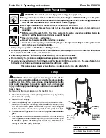
Setup
Locking
Nut
Lowering
Metering
Valve
Air
Locking
Nut
Raising
Metering
Valve
WARNING: The raising and lowering speeds of the
metering valves must be adjusted correctly before using the
jack the first time. If the valves are not adjusted correctly, the
jack could drop down too quickly under load, and personal
injury and/or equipment damage could occur as a result of the
loss of load.
Before using the transmission jack for the first time:
1. Close both metering valves (raising and lowering) by turning
them clockwise (CW).
2. Attach the air supply.
3. Set the lift speed by fully depressing the UP pedal and SLOWLY
turning the raising air metering valve counterclockwise (CCW)
until a comfortable speed is reached. Tighten the locking nut
behind the valve screw by turning it clockwise (CW) until tight.
4. To set the lowering speed, it is necessary to place a load on the
jack.
5. Fully depress the DOWN pedal and SLOWLY turn the lowering
metering valve counterclockwise (CCW) until a comfortable speed
is reached. Tighten the locking nut behind the valve screw by
turning it clockwise (CW) until tight.
l
l
l
l
l
l
l
l
l
l
l
l
l
l
l
l
l
l
l
l
•
Adequately support the vehicle before starting repairs.
•
Use of this product is limited to the removal, installation, and transportation in the lowered position of
transmissions, transfer cases, and transaxles.
•
Lower the jack slowly and carefully while watching the position of the load.
•
Do not modify the jack or use adapters unless approved or supplied by OTC.
•
Use only approved hydraulic fluid (Chevron AW Hydraulic Oil MV or equivalent). The use of alcohol or
hydraulic brake fluid could damage seals and result in jack failure.
This guide cannot cover every situation, so always do the job with safety first.
l
l
l
l
l


