


15
150 psig MWP
100%
234 sec.
90%
211 sec.
80%
187 sec.
70%
164 sec.
60%
140 sec.
50%
117 sec.
40%
94 sec.
30%
70 sec.
250 psig MWP
100%
174 sec.
90%
157 sec.
80%
139 sec.
70%
122 sec.
60%
104 sec.
50%
87 sec.
40%
70 sec.
30%
52 sec.
9B Cl OPEN CLOSED CLOSED
6" (
2
)
ECONOMIZER SWITCH
PURGE TIME
SETTING
TIME (Min.)
0 1 2 3 4 5 6 7 8 9 10
3A OPEN CLOSED
3B CLOSED OPEN
9B Cl 6" OPEN (1) Cl CLOSED
9A CLOSED Cl OPEN CLOSED
6" (1)
3.2.2.5 Tower status lights - indicate when left and right
towers are drying and regenerating.
3.2.2.6 Valve energized lights
Four LEDs are furnished on controller to indicate which air
control valves are energized at any particular time
3.2.2.7 Average Demand Meter
The demand meter displays the average demand on the
dryer for the last 4 cycles. It is determined by dividing 40 (time
to complete 4 cycles at full flow) by the actual time to complete
the last 4 cycles.
3.2.2.8 Tower pressure gauges
3.2.2.8.1 Periodically check tower pressure gauges to
verify that tower pressure gauge of tower on-line reads line
pressure and tower pressure gauge of tower off-line reads
below 2 psig.
NOTE
Read off-line tower gauge when tower is purging (air
exhausting from muffler)
3.2.2.8.2 Check mufflers for back pressure
Excessive back pressure may result due to the accumu-
lation of dust in the muffler. This sometimes occurs after start-
up because of dusting of the desiccant during tower filling and
dryer transport.
If the tower pressure gauge of the off-stream tower rises
out of the black area on the gauge dial, muffler elements
should be replaced. A set of purge exhaust muffler replace-
ment elements is supplied with the dryer.
3.2.3 All MODELS - Determine if air control valves are
operating and sequencing correctly.
Refer to Section 1.2 and Figure 1A and 1B for a general
description of operating sequence.
3.2.3.1 Inlet switching and purge/repressurization valves.
1) Tower pressure gauge of tower on-line should read line
pressure. No air should be leaking from purge/repressurization
valve of the on-line tower.
2) Tower pressure gauge of tower off-line should read below 2
psig while tower is purging. If excessive purge air is exhausting
during purge cycle, inlet valve may have failed to close or a check
valve may be sticking.
3.2.3.2 Check valves
Check valve sticking will result in excessive air discharge
through a muffler. If excessive air is discharged through the muffler
on the left, check if valve 5a or 5d is sticking. If excessive air is
discharged through the muffler on the right, check if valve 5b or 5c
is sticking.
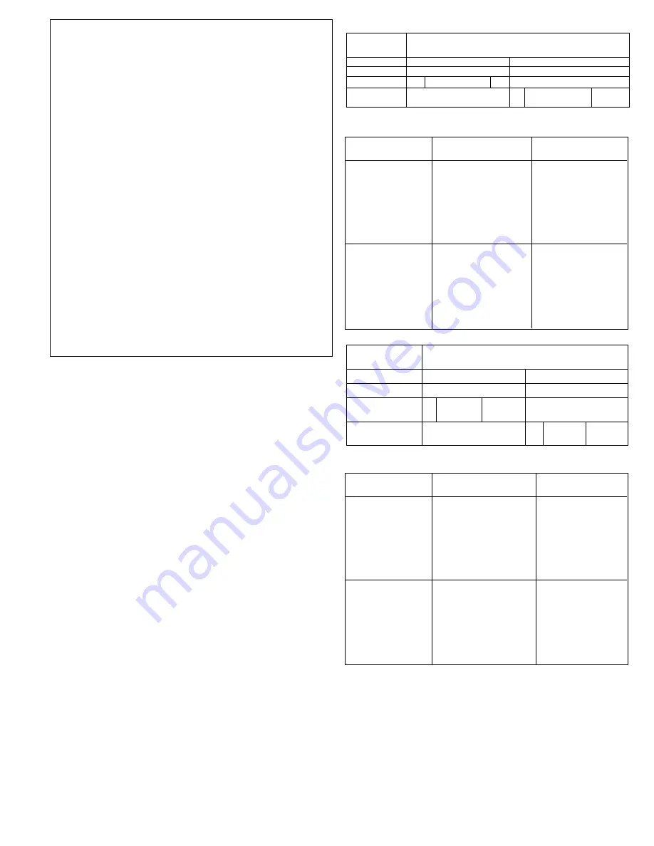
3.2.3.3 Operating Sequence
For dryers with standard controller and dryers with automatic
purge saving system operating on a fixed time cycle-
Figure 3C and Table 3C show valve sequence times when
dryer is operating on a 10 minute cycle.
Figure 3D and Table 3D
show sequence times when dryer is operating on a four minute
cycle.
TIME (MIN)
0 1 2 3 4
3A OPEN CLOSED
3B CLOSED OPEN
(1) See table 3C for open times.
VALVE
PRESSURE
9A CLOSED CI OPEN CLOSED
6" (
2
)
(2) See table 3D for open times.
3.3 Shut Down
3.3.1 Depressurize dryer
3.3.1.1 Open by-pass valve (if one is installed) and close inlet
and outlet isolation valves.
3.3.1.2 Run timer through a tower change cycle until pressure
gauges on both towers read 0 psig.
3.3.2 De-energize dryer
Turn dryer off using on-off switch (indicating lights extin-
guished).
3.4 Loss of Power
Control valves are designed so that upon loss of power the air
dryer is capable of drying air until the desiccant exposed to the air
flow is saturated.
TABLE 3D Purge valve open times for dryers operating on a 4 minute cycle.
VALVE
FIGURE 3D For dryers operating on a 4 minute cycle
TABLE 3C Purge valve open times for dryers operating on a 10 minute cycle.
FIGURE 3C For dryers operating on a 10 minute cycle
150 psig MWP
100%
66 sec.
90%
59 sec.
80%
53 sec.
70%
46 sec.
60%
40 sec.
50%
33 sec.
40%
26 sec.
30%
20 sec.
250 psig MWP
100%
42 sec.
90%
38 sec.
80%
34 sec.
70%
29 sec.
60%
25 sec.
50%
21 sec.
40%
17 sec.
30%
13 sec.
PRESSURE
ECONOMIZER SWITCH
PURGE TIME
SETTING