10
Typical applications
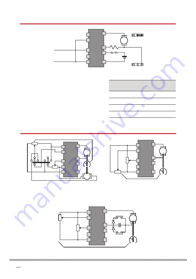
4.2 Torque control
3 A FUSE
ARM
5
6
7
1
2
3
4
9
8
200XL
V
COMMON OF
EXTERNAL SOURCE
0 TO ±5 V SIGNAL
FROM EXTERNAL
SOURCE
Bottom jumper
PID
AV
Top jumper
PID
PI
P
Sense
resistor
Insert a sense resistor in the A+ output, terminal
8. Reposition the bottom jumper to the AV
pin for the sense signal (the jumper pin is 0.8
mm square). The unit now outputs current in
proportion to the input voltage.
Turn the
MAX
preset fully anti-clockwise and set
the scaling by the sense resistor as shown in the
table. Use the
MAX
preset for fine adjustment of
the scaling factor.
Input
signal
Sense
resistor
Output
current
±5 V
1 Ω 6W
±2 A
±5 V
2 Ω 3W
±1 A
±5 V
4 Ω 1.5W
±0.5 A
±5 V
10 Ω 1W
±0.2 A
4.3 Position control
Figure 13 Torque circuit control
ARM
5
6
7
1
2
3
4
9
8
200XL
V
FWD
REV
TAC
+
10K
STOP
10K
SPINDLE ORIENT SYSTEMS
360° SENSOR POT
Figure 14 Position and speed
feedback with unit in PID mode
NOTE: If the Tacho is omitted, the speed is 100%.
ARM
5
6
7
1
2
3
4
9
8
200XL
V
10K
10K
POSITION SENSOR POT
POSITION
REFERENCE
Figure 15 Position feedback
with unit in PID mode
rev only
fwd only
0.1 µF
ARM
5
6
7
1
2
3
4
9
8
200XL
V
10K
POSITION SENSOR POT
POSITION
REFERENCE
10K
DIODE TYPE 1N5401
Figure 16 Position feedback with end of travel limit
Содержание 200XLV
Страница 6: ......


