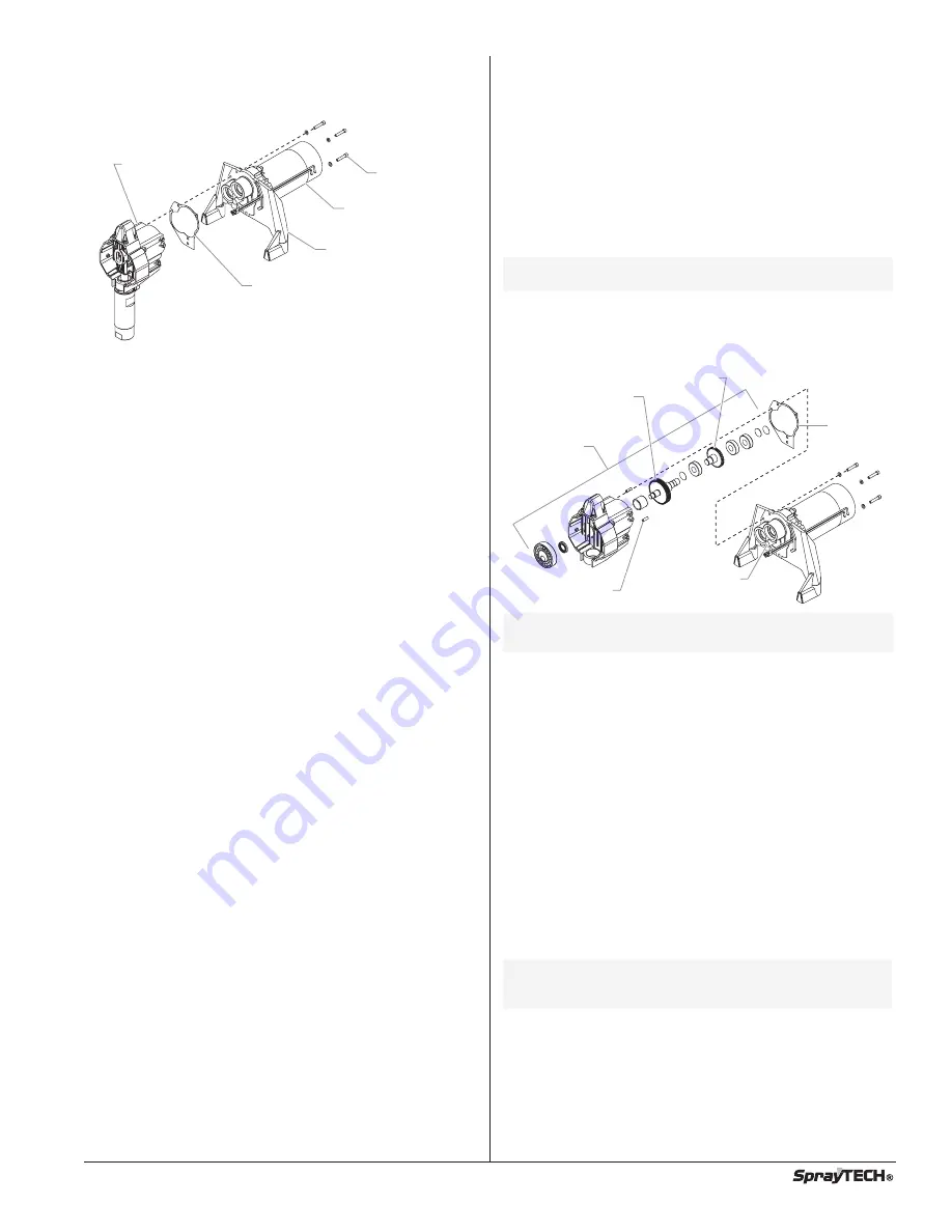
15. Using a hex wrench, loosen and remove the three adapter
plate screws and flat washers that hold the motor/adapter
plate assembly to the gear box housing. Pull the
motor/adapter plate assembly off of the gear box housing.
16. With the motor removed, inspect the gears in the gear box
housing for damage or excessive wear. Replace the
gears, if necessary.
17. Align the two dowel pins on the gear box housing with the
holes on the new motor/adapter plate assembly and install
the motor/adapter plate assembly onto the gear box
housing. Make sure the housing gasket is positioned
properly.
18. Apply blue LocTite to the three adapter plate screws.
19. Secure the motor/adapter plate assembly to the gear box
housing with the three adapter plate screws and washers.
Torque to 156–180 in./lbs.
20. Slide the baffle over the end of the motor and position it in
the location noted during disassembly.
21. Position the pump on the cart. Secure the pump to the
cart using the four pump mounting screws, lock washers,
and flat washers.
22. Position the filter bracket on the adapter plate. Secure the
filter bracket with the two filter bracket screws, lock
washers, and flat washers.
23. Thread the transducer into the filter housing. Tighten
securely.
24. Position the filter assembly on the filter bracket. Secure
the filter using the two filter assembly screws and lock
washers.
25. Reconnect the phone jack-style connector on the black
wire from the transducer to the socket on the pressure
control assembly.
26. Connect the red wire from the motor to the red wire on the
rectifier in the pressure control assembly (refer to the
electrical schematic in the Parts List section of this manual).
27. Connect the black wire from the motor to the black wire on
the rectifier in the pressure control assembly (refer to the
electrical schematic in the Parts List section of this manual).
28. Position the pressure control assembly on the gear box
housing. Secure the pressure control assembly with the
four pressure control assembly screws.
29. Attach the high-pressure hose to the nipple on the back of
the fluid section and to the bottom of the filter assembly.
Tighten with a wrench. Do not kink the hose.
30. Slide the motor shroud over the motor and the baffle.
Make sure the baffle stays in position.
31. Secure the motor shroud to the adapter plate with the
three motor shroud screws.
32. Place the front cover on the gear box housing and secure
in position using the six front cover screws.
33. For Upright cart units, thread the siphon tube into the inlet
valve and tighten securely. Make sure to wrap the threads
on
the down tube with
PTFE
tape before assembly. Replace
the return hose into the clamp on the siphon tube.
34. For Low Boy cart units, insert the elbow on the suction set
assembly into the bottom of the inlet valve housing. Push
the retaining ring up into the groove inside the inlet valve
housing to secure the suction set assembly in position.
Motor
Adapter Plate
Housing Gasket
Adapter Plate
Screw
Gear Box
Housing
Replacing the Gears
1. Perform the Pressure Relief Procedure and unplug the unit.
2. Perform steps 2–15 of the “Replacing the Motor
Assembly” procedure in this section.
3. Inspect the armature gear on the end of the motor for
damage or excessive wear. If this gear is completely
worn out, replace the motor.
4. Remove and inspect the 1st stage gear set for damage or
excessive wear. Replace, if necessary.
5. Inspect the output gear assembly for damage or
excessive wear. If damaged or worn, replace the front
gear box assembly.
6. Position the housing gasket on the two dowel pins on the
gear box housing.
7. Perform steps 17–34 of the “Replacing the Motor
Assembly” procedure in this section.
Replacing the Transducer
1. Perform the Pressure Relief Procedure and unplug the unit.
2. Loosen and remove the four pressure control assembly
screws. Carefully pull the pressure control assembly off of
the gear box housing.
3. At the pressure control assembly, disconnect the phone
jack-style connector on the black wire coming from the
transducer.
4. Set aside the pressure control assembly.
5. Loosen and remove the two filter assembly screws. Lift
the filter assembly off of the filter bracket.
6. Using a wrench, loosen and remove the transducer from
the filter housing. Carefully thread the transducer wire out
through the hole in the gear box housing.
7. Thread the new transducer wire through the hole in the gear
box housing and over to the pressure control assembly.
8. Thread the new transducer into the filter housing and
tighten securely with a wrench.
9. Position the filter assembly on the filter bracket. Secure
the filter using the two filter assembly screws and lock
washers.
10. Reconnect the phone jack-style connector on the black
wire from the transducer to the socket on the pressure
control assembly.
11. Position the pressure control assembly on the gear box
housing. Secure the pressure control assembly with the
four pressure control assembly screws.
NOTE: Make sure the o-ring on the transducer is in
place before threading the transducer into the
filter housing.
NOTE: The front gear box assembly does not include
the 1st stage gear set.
Armature Gear
1st Stage
Gear Set
Dowel Pin
Front
Gear Box
Assembly
Output
Gear
Assembly
Housing
Gasket
NOTE: Clean and refill the gear box cavity up to the rear
face of each gear with grease (P/N 9870307).
© SprayTECH. All rights reserved.
9
Содержание EPX2305
Страница 14: ......


