8. Locate the clutch hub and armature assembly on the end
of the engine shaft. Note the two set screws as well as
the unused, threaded hole in the taper lock bushing at the
center of the clutch hub.
9. Using an 1/8” hex wrench, remove the two set screws
from the taper lock bushing
10. Thread one of the set screws into the unused, threaded hole
on the taper lock bushing. As the screw tightens, the bushing
will loosen. Once the bushing has loosened enough, slide the
clutch hub and armature assembly off the engine shaft.
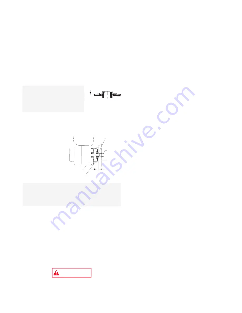
11. Before replacing the clutch
hub and armature assembly
the proper “set back” must
be created. Using the
SprayTECH hub set-up tool
(P/N 0509925), create a “set
back” of 0.20” between the
friction surface of the clutch
armature and the forward face of the clutch hub.
12. Line up the three holes in the taper lock bushing with the
three holes in the clutch hub and insert the bushing into
the center of the clutch hub.
13. Line up the key on the taper lock bushing with the keyway
on the engine shaft and slide the assembly onto the shaft
with the holes facing out.
14. Apply blue Loctite to the
two set screws and insert
the screws into the taper
lock bushing. Tighten the
set screws only two turns
at this time.
15. Line up the forward face
of the clutch hub with the
front face of the clutch
housing. Using an 1/8”
hex wrench, alternately
tighten the set screws
into the taper lock bushing. Torque to 65–75 in/lbs.
16. Make sure the friction surface of the clutch armature is
clean and free from oil or grease.
Removing the Clutch Rotor, Clutch Field, and
Drive Shaft Assembly
1. Follow steps 1–7 in “Removing/Replacing the Clutch Hub
and Armature Assembly.”
2. Locate the clutch rotor assembly on the end of the drive shaft
assembly. Note the locations of the three socket screws and
the two empty, threaded holes on the clutch rotor.
3. Using a 3/16” hex wrench, remove the three socket
screws and lock washers that secure the clutch rotor to
the drive shaft assembly.
4. Thread two of the socket screws into the empty, threaded
holes and tighten alternately. This will push the clutch
rotor away from the drive shaft assembly and pinion.
Electrostatic discharge (ESD) potential could cause
damage to electronic pressure control. Use SprayTECH
ESD wrist strap P/N 0507958 or equivalent when working
on electronic pressure control.
WARNING
NOTE: To ensure the clutch hub and the clutch
housing are aligned, hold a straight edge
across the face of the clutch housing and then
hold the clutch hub against the back of the
straight edge while tightening the two set
screws into the taper lock bushing.
Clutch
Housing
0.20"
Engine
Set
Screw
Straight
Edge
Taper
Lock
Bushing
NOTE: A new clutch hub and
armature assembly will
come pre-assembled, but
the “set back” will not be
correct. The “set back”
must still be created using
the hub set-up tool.
0.20"
Содержание 509009
Страница 19: ......
Страница 22: ...22 SprayTECH All rights reserved Parts List Main Assembly...
Страница 24: ...24 SprayTECH All rights reserved Fluid Section Assembly P N 0509144...


