background image

1

2

4
4

6
6
9

11

12
12
12
13
15

16
16
16
17
18

19
19
20

22

23

25

26

27

28

TABLE OF CONTENTS

1. INTRODUCTION...................................................................................................

2. IMPORTANT SAFETY PRECAUTIONS................................................................

3. ASSEMBLING YOUR TREADMILL......................................................................

List of Parts...........................................................................................................

4. TREADMILL ASSEMBLY.......................................................................................

Pedestal and Handle Assembly Steps.................................................................
Display Installation Steps......................................................................................
Connect to Power..................................................................................................

5. T670 DISPLAY......................................................................................................

Display Features...................................................................................................
Display Features..................................................................................................
Button Functions..................................................................................................
Safety Key............................................................................................................

6. HOW TO USE YOUR T670 TREADMILL............................................................

Quick Start............................................................................................................
Workout Setup.....................................................................................................
Operating Prodcedure during Excercise..............................................................
Cool Down ..........................................................................................................

7. PROGRAMS.......................................................................................................

Program List........................................................................................................
User Parameter Setting.......................................................................................

8. GUIDELINES FOR EXERCISE...........................................................................
.
9. ADJUST THE WALK BELT..................................................................................

10. FLOOR LEVEL ADJUSTMENT.........................................................................

11. MAIN FUSE FAILURE.......................................................................................

12. ERROR MESSAGE...........................................................................................

13. WIRING SCHEMATIC........................................................................................

Содержание T670

Страница 1: ...ssembly Steps Display Installation Steps Connect to Power 5 T670 DISPLAY Display Features Display Features Button Functions Safety Key 6 HOW TO USE YOUR T670 TREADMILL Quick Start Workout Setup Operat...

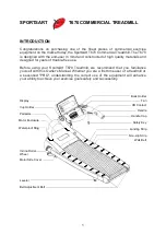
Страница 2: ...Before using your SportsArt T670 Treadmill we recommend that you familiarize yourself with this Owner s Manual Whether you are a first time user of a treadmill or a seasoned PRO understanding the corr...

Страница 3: ...ng DO NOT wear loose clothing DO NOT wear shoes with leather soles or high heels Tie all long hair back Use care when mounting and dismounting the unit DO NOT use any accessories that aren t specifica...

Страница 4: ...ergo a complete physical examination DO NOT stand on the belt when starting Straddle the belt with your feet on the right and left landing strips To reduce the risk of electric shock Always unplug thi...

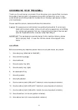
Страница 5: ...from the container rather than lifting it The packaging is specially design for the machine delivery please have it properly kept in case the machine needs to be shipped in the future Before assemblin...

Страница 6: ...et head screw For handlebars On the treadmill 20 Four D17 d8 3 t2 mm flat washers For handlebars On the treadmill 21 Four M6 L10 hex head screw For use on display On the treadmill Some parts may get m...

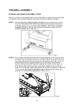
Страница 7: ...stal Then hold the right pedestal onto the support bracket on the right side of the treadmill Secure the right pedestal by fastening the bolts with washers as shown Hold the left pedestal onto the sup...

Страница 8: ...the right pedestal through the right handle C D E Remove the tie on the data cable set Use the to tighten the bolts with washers fixing the handlebars in place on the bracket Finally put the left and...

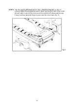
Страница 9: ...estal screws in place then put the side covers both left and right in place FG and secure them with the Phillips head screws Finally set the waterproof rings in place near the hood See Fig 5 ALLEN WRE...

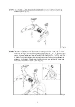
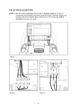
Страница 10: ...the to remove the four bolts from location A shown below Hold the display into position and connect data cables See Fig 6 1 6 3 Use the to secure the cable ALLEN WRENCH WITH THE T SHAPED HANDLE 5 mm C...

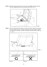
Страница 11: ...ack without pinching the wires See Fig 7 With one hand behind the display for support push the display down gently until it connects securely If it does not connect securely please try again Proceed t...

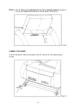
Страница 12: ...ure the display with the bolts as shown below See Fig 9 Connect the power cable as indicated in Fig 10 and secure it by tightening the screws HEX ALLEN WRENCH WITH THE T SHAPED HANDLE 5 mm CONNECT TO...

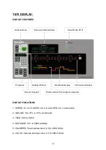
Страница 13: ...5 increments 3 TIME 0 00 to 99 59 4 DISTANCE 0 01 to 9999 Km Mile 5 CALORIES Total calories burnt 0 0 to 9999 KCAL 6 CAL Hr Calories burnt per hour 0 0 to 999 9 KCAL 12 Workout Goal Personal CardioAd...

Страница 14: ...press ENTER to confirm your choice 6 NUMERIC KEYPAD 0 to 9 The numeric keypad can replace the function of buttons Simply enter numbers 0 to 9 on the numeric keypad rather than pressing buttons 7 DECIM...

Страница 15: ...oss workout 17 CARDIO The cardio program keeps the user s heart rate at 80 of maximum i e 220 AGE 0 8 to provide an optimal cardio workout 18 CUSTOM HR The Heart Rate Control HRC program allows users...

Страница 16: ...press LOCK to continue to view the current feedback type c When the feedback mode is locked press the UNLOCK button to unlock it and view other feedback types 1 The safety key must be in place for th...

Страница 17: ...00 default value 30 00 a When pressing TIME the minute value flashes continuously b Press or the numeric keypad to select the time c Press ENTER to confirm your choice 2 Set up DISTANCE From 0 10 to 9...

Страница 18: ...0K there are two options FLAT HILL The message row shows 1 FLAT 2 HILL a Press 1 or 2 on the numeric keypad to select FLAT or HILL b Pressing ENTER directly selects the default FLAT 4 When the previou...

Страница 19: ...rams WORKOUT GOAL TIME DISTANCE CAL counts up continuously Upon achieving the WORKOUT GOAL TIME DISTANCE CAL the electronics displays ACCU DATA accumulative data for your workout After displaying the...

Страница 20: ...3 2 2 A Press 1 2 or 3 on the numeric keypad to select one of the three INTERVAL modes B Pressing INTERVAL while exercising can switch to a different INTERVAL mode C While exercising you can change t...

Страница 21: ...essage row will display NO HEART RATE READING PLEASE CHECK TRANSMITTER If the heart rate cannot be detected either by the contact grips or transmitter SPEED or INCLINE will not increase or decrease au...

Страница 22: ...out changing parameters 4 Display the version of the software a The message row will display the version of the control board CTL XXXXX XX Press ENTER to confirm your choice or press STOP to quit with...

Страница 23: ...hould always start slowly and bring their workout sessions up to 20 minutes or more As your fitness level increases you will be able to maintain your heart rate in the training zone for longer periods...

Страница 24: ...auge indicates misalignment The belt should center in the middle of the green area 2 If the belt is in the red mark on either side of the deck follow the steps below to align the walk belt 3 Turn off...

Страница 25: ...gauge When the belt is back in the green safety zone you can continue your regular use of the treadmill Slowly increase the speed of the unit to 5 5 MPH 9 KPH and let it run for at least 45 seconds M...

Страница 26: ...c weights The treadmill will not stop immediately if any object becomes caught in the belt or rollers Over tightening of the belt would causes damage and premature failure of the precision bearings in...

Страница 27: ...the main fuse push the fuse holder toward the machine and turn it counterclockwise then pull out the fuse holder Remove the fuse from the holder Insert a new fuse of the appropriate type into the fuse...

Страница 28: ...tor suddenly accelerated Please re start the unit ERROR_2_1_ The IGBT current is too high Please re start the unit ERROR_2_2_ The IGBT is too hot Speed is restricted to half ERROR_3_1_ The elevation m...

Страница 29: ...Wiring Schematic 28 Your Authorized Distributor T670...

Отзывы: