background image

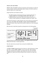
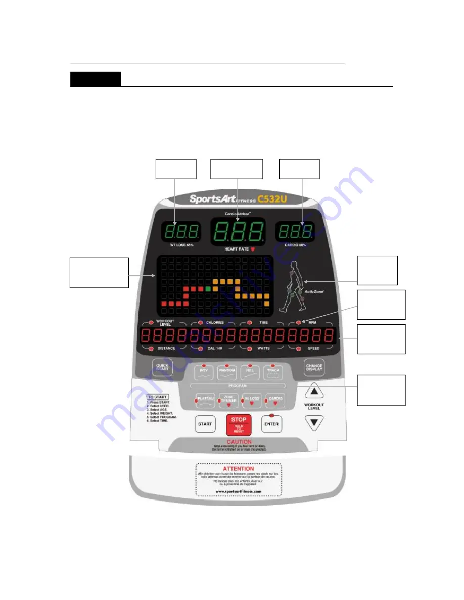
UNDERSTANDING THE C532U DISPLAY CONSOLE

The C532U exercise bike is designed for user convenience. With better feedback
about your workout, you get better results. The following explains the display key and
window functions. Please read this manual, understand the display functions, and
thereby get optimum enjoyment and benefit from this product.

23

65% HR
TARGET

HEART RATE

80% HR
TARGET

BODY
AREA
LED

SCAN
INDICATOR

FEEDBACK
WINDOW

DOT MATRIX
WORKOUT
ILLUSTRATION

WORKOUT
PROGRAM
KEYS

DISPLAY

Overview

Содержание C532U

Страница 1: ...t STEP8 Adjusting the Seat Position STEP9 How To Connect The Ground Wire 5 UNDERSTANDING THE C532U DISPLAY CONSOLE DISPLAY Overview DISPLAY Windows DISPLAY Keys DISPLAY Specifications 6 EXERCISE OPERA...

Страница 2: ...ouble free usage the C532U exercise bike will become an integral part of your fitness regimen Before using your C532U exercise bike we recommend that you familiarize yourself with this Owner s Manual...

Страница 3: ...2 IMPORTANT SAFETY PRECAUTIONS...

Страница 4: ...a 3...

Страница 5: ...4 e a...

Страница 6: ...5...

Страница 7: ...A4 A5 Pedestal Handlebar mount upper and lower cover Handlebar Pedestal cover Main frame and body 1 1 1 1 1 1 1 1 1 1 Hardware kit Seat bottom Left right pedals Rear support Rear support cover Assembl...

Страница 8: ...ated washer L shaped Allen wrench L shaped Allen wrench Double open end wrench Screwdriver handle Screwdriver bit No Part Name Specification 31 Components on the Product 33 34 32 M4 L16 Inner hex scre...

Страница 9: ...f the bike on the flattened cardboard A First remove the parts and cut the four corners of the box to flatten them B Lift the front end of the box and remove the Styrofoam C Lift the back end of the a...

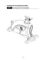
Страница 10: ...Rear Support and Cover Installation STEP 1 ASSEMBLING YOUR BIKE EXERCIS E E 9...

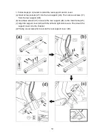
Страница 11: ...support A8 Then remove screws 31 from the rear support A8 b Use these screws 31 to secure the rear support A8 to the main frame A5 c Align the support cover A9 with the left and right side covers The...

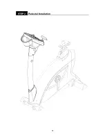
Страница 12: ...Pedestal Installation STEP 2 11...

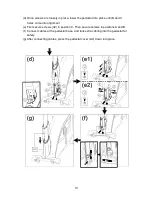
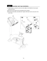
Страница 13: ...ower part of the pedestal A1 Note Areas A and B have elongated holes Area C has round holes b Insert the pedestal cover A4 onto the pedestal A1 as shown c Insert the pedestal A1 onto the pedestal base...

Страница 14: ...B and C holes come into alignment e First secure screws 32 in position C Then secure screws in positions A and B Connect cables at the pedestal base and tuck extra cabling into the pedestal for safet...

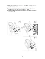
Страница 15: ...EP 3 14 a b 3 Follow steps a e below to secure the handlebar and handlebar mount upper and lower covers a Remove screws 33 from the handlebar A3 as shown b Remove screws 34 and disconnect upper and lo...

Страница 16: ...cure the handlebar mounting screws d After securing handlebar mount screws connect wires in the pedestal and handlebars Then tuck wires into the handlebar for safety e Connect handlebar mount upper an...

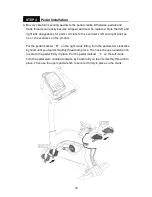
Страница 17: ...hand until you feel it smoothly thread into place Then use the open end wrench to secure the pedal firmly in place Put the pedal marked L on the left crank Turn the pedal stem counterclockwise by hand...

Страница 18: ...17 Seat Installation 5 First remove nuts 35 from the seat bottom A6 Set the seat bottom in place and secure it with the nuts 35 STEP 5...

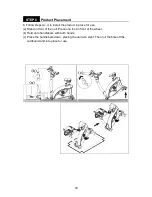
Страница 19: ...all the product in place for use a Stand in front of the unit Place one foot in front of the wheel b Hold onto handlebars with both hands c Press the handlebars down placing the unit at a slant Then r...

Страница 20: ...wobbles in use It should rest flat on the floor If necessary follow steps a b c to level the unit a Loosen the leveler nut b Rotate the leveler foot so that it touches the floor c Then secure the leve...

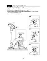
Страница 21: ...eat height a Turn the seat adjustment knob counterclockwise Then pull the knob b Use your hand to adjust the seat position up or down c When the seat is in the desired position release the knob Then t...

Страница 22: ...t seat fore and aft placement d Press the fore aft adjustment lever downward to release the seat e Use your hand to move the seat fore or aft as desired f Lift the fore aft adjustment lever upward to...

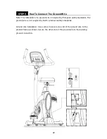
Страница 23: ...The ground wire is not required by North American safety standards Ground wire installation Use a screw to secure one end of the ground wire to the product frame as shown Secure the other end of the g...

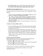
Страница 24: ...ter results The following explains the display key and window functions Please read this manual understand the display functions and thereby get optimum enjoyment and benefit from this product 23 65 H...

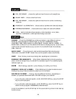
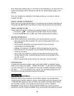
Страница 25: ...first entering user information In QUICK START mode time counts upward values accumulate Press this key to start exercising after inputting user information When these indicators flash or during exer...

Страница 26: ...K CAL CAL Hr calories per hour 0 0 999 9 K CAL RPM rotations per minute 0 200 countable HEART RATE range 40 250 WATTS 0 9999 SPEED 0 55 9 mile hour or 0 90 hour 1km 0 62137 mile 1 mile 1 60935km PROGR...

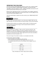
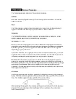
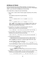
Страница 27: ...T key and begin exercising Then press resistance level keys to directly control workout resistance Or press workout program keys to activate a specific workout The default age and weight 35 years old...

Страница 28: ...target heart rates and calorie expenditure information 1 Press the keys to select a user age 2 Press the ENTER key to confirm your choice and proceed to set the user weight 3 Press the keys to select...

Страница 29: ...e program you can activate another program Time continues to accrue If you enter one workout from another workout after activating a user ID workout distance time and calorie values continue to accumu...

Страница 30: ...indicates one interval of one minute in duration followed by a second interval of two minutes in duration Each time the interval key is pressed one of the two interval programs appears When your prefe...

Страница 31: ...tected the message NO HEART RATE READING PLEASE CHECK TRANSMITTER appears At this time while no heart rate is detected resistance can only be adjusted manually When heart rate control starts operating...

Страница 32: ...ONE TRAINER key before you start to exercise does not activate this program It also requires reception of a heart rate signal Other aspects of ZONE TRAINER are similar to WT LOSS and CARDIO programs H...

Страница 33: ...ither metric or imperial units of measure appear depending on the existing setting The feedback windows show the present setting Imperial Metric Press keys to toggle from one unit setting to another W...

Страница 34: ...ation free from interfering items 4 Place fitness products apart by at least 100 cm to avoid having the heart rate value from an exerciser on one product appear on another product 5 Heart rate values...

Страница 35: ...In cold dry areas static electricity can interfere with unit operation In such environments touching metal may cause shocks from static electricity Suggestions Before touching metal touch a material...

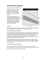
Страница 36: ...cise session depends on your fitness level In general it is recommended that you maintain your heart rate in the training zone for at least 15 to 20 minutes to realize an aerobic benefit Beginners sho...

Страница 37: ...owel to clean the arms and handles 1 Turn off and unplug the unit if applicable Remove the cover Wait five minutes to ensure there is no power to the drive board Vacuum carefully Avoid bumping wires o...

Страница 38: ...r cord 2 Pedestal 3 Pedals straps seat carriage Months 1 3 Months 4 6 Month 7 9 Month 10 12 1 2 Yearly Tasks 1 Vacuum 2 Drive belt First half of the year Second half of the year Notes Facility Name Ma...

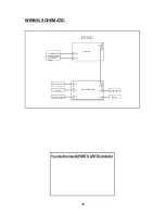
Страница 39: ...8 Your Authorized SPORTS ART Distributor CON1 CON3 CON2 CTL Board C532U CN3 CN6 CN1 CN2 CN5 DRIVER BOARD CN4 Speed Sensor Battery HTR BOARD Telemetry heart rate receiver board Battery charger Alternat...

Отзывы: