Liquid ControLs Group
An IDEX Fluid & Metering Business
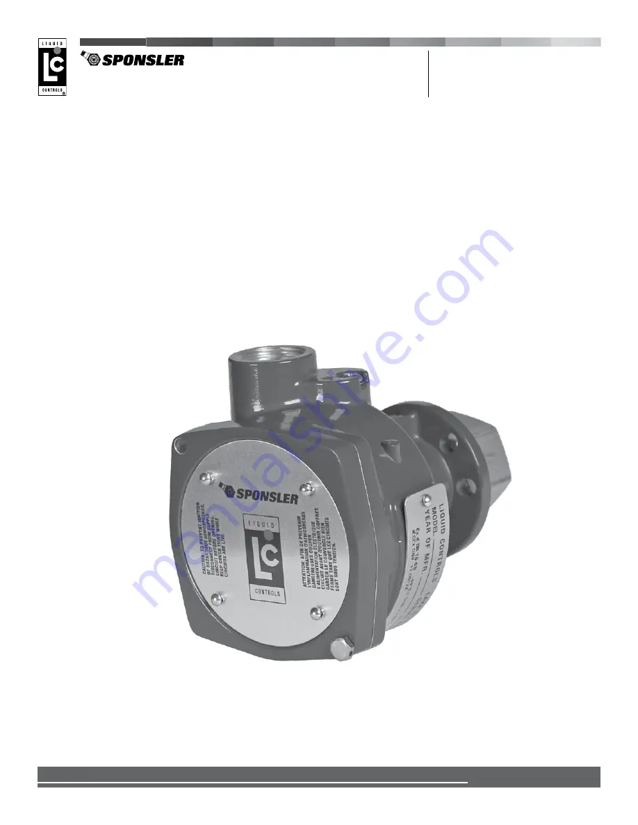
Sponsler SP714-S2i
Pulse Amplifier
Installation & Parts
Operation: EM700-10
Страница 1: ...Liquid Controls Group An IDEX Fluid Metering Business Sponsler SP714 S2i Pulse Amplifier Installation Parts Operation EM700 10...
Страница 2: ...strictly in the hands of the owner operators of the equipment Neglect of that responsibility is not within the control of the manufacturer NOTICE The most current English versions of all Liquid Contr...
Страница 3: ...fire department state and local codes to ensure adequate preparation Read this manual as well as all the literature provided in your owner s packet Save these instructions for future reference Failur...
Страница 4: ...40 to 176 F 40 to 80 C Storage 76 to 257 F 60 to 125 C Specifications Input Voltage 6 28 VDC 83 mA maximum 24 VDC Protected against polarity reversal Signal Input Frequency 2 kHz maximum over operatin...
Страница 5: ...y voltage Vcc 4 28 VDC Total System Resistance 500 minimum 28 VDC Output Voltage Logic HIGH Vcc 1 VDC Logic LOW 0 25 VDC Output Current Logic HIGH 8 to 60 mA DC Logic LOW 8 mA DC DC power supply volta...
Страница 6: ...eratures above 70 C use field wiring suitable for 20 C above maximum ambient temperature II Suitable for use in surface not mine installations 2 G High level of protection is provided against flammabl...
Страница 7: ...uration translates the output signal from the turbine flowmeter s pickup coil into a current value 2 wire connections are effective transmitting the signal over long distances The 3 wire TTL Sourcing...
Страница 8: ...llator SW2 and or check the diagnostic operational LEDs D1 D2 See page 11 9 Coil the wires underneath the CPU board and place the board inside the housing ensuring the wires are not pinched and replac...
Страница 9: ...using the information below 7 Wire the SP714 S2i to the pulse acquisition device and DC power supply as indicated in the schematic 8 If necessary adjust the input signal sensitivity R1 activate the di...
Страница 10: ...n the schematic 8 If necessary adjust the input signal sensitivity R1 activate the diagnostic test oscsillator SW2 and or check the diagnostic operational LEDs D1 D2 See page 11 9 Coil the wires under...
Страница 11: ...equency is above 40 Hz the light will flash very quickly and the LED will appear to be constantly illuminated If the input into the SP714 S2i stops on a positive portion of the signal pulse the LED wi...
Страница 12: ...rive Lake Bluff IL 60044 847 295 1050 SAMPI Via Amerigo Vespucci 1 55011 Altopascio Lucca Italy 39 0583 24751 IDEX Fluid and Metering Pvt Ltd Survey No 256 Alindra Savli GIDC Manjusar Dist Vadodara 39...