8 |
EN | instruction
EN USE’S MANUAL
Thank you for purchasing the Magnetic Bike. Before operating this unit, please read this manual carefully to
ensure optimum performance and safety.
1. IMPORTANT
SAFETY INFORMATION
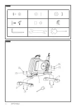
2. HARDWARE TOOLS FOR INSTALLATION
(see fig A /B):
1. Be aware of your body’s signals. Incorrect or excessive exercise
can damage your health. If you do experience any of these
conditions you should consult your doctor before continuing
with your exercise program.
2. Keep children and pets away from the equipment. The equip-
ment is designed for adult use only.
3. Use the equipment on a solid, flat level surface with a pro-
tective cover for our floor or carpet. For safety, the equipment
should have at least 0.5 meter of free space all around it.
4. Before using the equipment, check the nuts and bolts are se-
curely tightened. Some parts like pedals, etc. It’s easy to be
ware away.
5. Always use the equipment as indicated. If you find any
defective components whilst assembling or checking the
equipment, or if you hear any unusual noise coming from the
equipment during use, stop. Do not use the equipment until
the problem has been rectified.
6. Wear suitable clothing whilst using the equipment. Avoid
wearing loose clothing which may get caught in the equip-
ment or that may restrict or prevent movement.
7. The equipment has been tested and certified to EN957 under
class H.C.
Suitable for domestic, home use
only.
Maximum user weight 120 kg.
8. The equipment is not suitable for therapeutic use.
3. ASSEMBLING INSTRUCTIONS
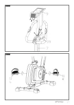
STEP 1 (see fig C):
Fix the rear & front stabilizer ( 2 )&(3)on the main frame (1) with
four sets of flat washer(15), domed nut(16) and bolt(14) tightly
by multi-function spanner
Note:
the front stabilizer is with transport wheels.
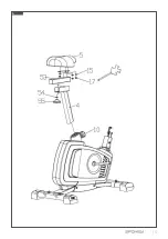
STEP 2 (see fig D):
Loosen the adjusting knob(10) and pull it out first before sliding
the seat support post(4) into the seat support post housing on
the main frame (1), and align holes for your desired height ,then
STEP 3 (see fig E):
Put the front post(7) into the decorative part(6) first, then
connect the resistance adjuster wire (21) with (23), as well the
console wire (22)with (24).please do it carefully following the
assembly photo as attached. Fix the front post(7) on the ma-
in frame with two sets of mushroom head allen screw (18)&
Waved washer (20) and two sets of mushroom head allen screw
(18)&flat washer(15) properly by allen spanner. Then fix the de-
corative part(6) into the plastic cover.
STEP 4 (see fig F):
Take out the protective plug (65) , and put the two pieces of wires
on the handle bar into the protective plug first , then into the
hole ,after that put the protective plug (65) back into the hole.
Fix the handle bar(8) on the handle bar fixing socket with T-shape
knob(62), casing(63) & Decorative plastic part(64).
STEP 5 (see fig G):
Screw out the Cross recess head screw(19) from the console (9),
and connect the console wires properly, then align the console (9)
with the plate welded on the front post(7), then fix the console
(9) with the cross recess head screw(19) tightly by multi-function
spanner.
STEP 6 (see fig H):
Fix the pedal(11L) which is marked „L” on the crank(28L) marked
„L” tightly by 15/19spanner in anticlockwise, then fix the pedal
(11R) which is marked „R” on the crank(28R) marked „R” tightly
by 15/19spanner in clockwise.
Now the equipment is completed assembled, if you find it not le-
veled on the floor, you can adjust it by the adjusting rear stabilizer
tube plug(13).
release the adjusting knob and tighten it properly. then fix the
seat (5) on the seat sliding set properly by multi-function span-
ner.
Note:
Do not exceed the mark „stop”.
Содержание EDO PRO 940638
Страница 2: ...2...
Страница 3: ...3 A...
Страница 4: ...4 C B...
Страница 5: ...5 D...
Страница 6: ...6 E F...
Страница 7: ...7 G H...


