Spirax Sarco LP30 Скачать руководство пользователя страница 14

IM-P402-44 

 AB Issue 15

14

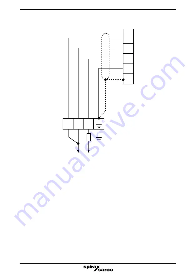
Fig. 10  Standard version

Comparator tip

*

 Internal resistor

Black

Black

Red

Yellow

Screen

*

Internal link

Low alarm tip

LP30 connector

Ensure that resistance from 

the probe body to boiler shell 

is less than 1 

.

LC3050 controller

50

51

52

53

54

Содержание LP30

Страница 1: ...uct information 3 Installation 4 Wiring 5 Probe clearance test procedure 6 Maintenance 7 Spare parts IM P402 44 AB Issue 15 4024750 15 Copyright 2015 Printed in GB LP30 High Integrity Self monitoring Low LevelAlarm Probe Installation and Maintenance Instructions ...

Страница 2: ...IM P402 44 AB Issue 15 2 ...

Страница 3: ...ded in the system to prevent such over limit situations iii Determine the correct installation situation and direction of fluid flow iv Spirax Sarco products are not intended to withstand external stresses that may be induced by any system to which they are fitted It is the responsibility of the installer to consider these stresses and take adequate precautions to minimise them v Remove protection...

Страница 4: ...10 Protective clothing Consider whether you and or others in the vicinity require any protective clothing to protect against the hazards of for example chemicals high low temperature radiation noise falling objects and dangers to eyes and face 1 11 Permits to work All work must be carried out or be supervised by a suitably competent person Installation and operating personnel should be trained in ...

Страница 5: ...ed a safety requirement In this case the relays must simultaneously isolate the feedwater supply and the boiler heat supply at high alarm status All boiler water limiters alarms require regular functional testing Under certain circumstances the water level in a boiler can be different to that shown in the gauge glass Separate literature is available from Spirax Sarco on this subject Do not install...

Страница 6: ... maximum cold hydraulic test pressure of 60 bar g 870 psi g 2 4 Technical data Maximum probe cable length 50 metres 164 ft 2 5 How the LP30 works The probe has a level sensing tip probe tip and a comparator tip The earth return path is via the body connection Under normal operating conditions the probe tip is immersed and the resistance to earth is low When the water level drops below the probe ti...

Страница 7: ... 1 LP30 Standard version Fig 2 LP30 UL version Cable socket Pg 11 cable gland Probe body 27 A F BSP taper connection Probe tip 4 off 18 AWG flying leads 300 mm 12 long NPT conduit thread adaptor NPT taper connection Comparator tip ...

Страница 8: ...Figure 3 Wherever possible the boiler manufacturer should be consulted for advice on the working and alarm water levels Boiler cold Boiler firing Level gauge glass 2nd low 1st low Fig 3 Typical low alarm levels 2nd low 1st low 3 2 Protection tube The probe must be installed in a protection tube when used as a low level alarm in a steam boiler The protection tube provides a relatively steady water ...

Страница 9: ...IM P402 44 AB Issue 15 9 Boiler shell 20 mm vent hole as high as possible 20 mm Fig 4 Typical protection tube Minimum Ø 80 mm ...

Страница 10: ...hreaded end of the connector is allowed to rotate in the probe body the internal wiring will be damaged Screw the probe tip onto the probe until the hole in the probe lines up with the bottom of the slot in the probe tip see Figure 5 Support the assembly and tap in the retaining pin until an equal length protrudes from each side of the probe tip Tighten the lock nut onto the probe tip 5 7 N m 4 5 ...

Страница 11: ...ad will not bottom out i e probe body hexagon contacts the face of the female screwed connection unless there is excessive wear or an out of tolerance female thread in which case it will be necessary to replace or re work the flange or connection 3 3 3 Subsequent removal and refitting WARNING Ensure boiler or vessel is depressurised and vented to atmosphere before attempting to unscrew or remove t...

Страница 12: ...an and undamaged To gain access to the connector block within the cable socket remove the central screw and withdraw the hinged cover The connector block on the standard LP30 maybe rotated in 90 steps to facilitate wiring Remove the retaining screw and withdraw socket Remove connector block and reposition as required Note It is not possible to rotate the connector block on the UL FM version 4 Wiri...

Страница 13: ...Yellow Black Black Red Yellow Screen Internal link Screen Internal link Low alarm tip Comparator tip Low alarm tip LP30 connector Ensure that resistance from the probe body to boiler shell is less than 1 LP30 connector Ensure that resistance from the probe body to boiler shell is less than 1 LC3000 controller LC3000 controller 9 10 11 12 9 10 11 12 ...

Страница 14: ...10 Standard version Comparator tip Internal resistor Black Black Red Yellow Screen Internal link Low alarm tip LP30 connector Ensure that resistance from the probe body to boiler shell is less than 1 LC3050 controller 50 51 52 53 54 ...

Страница 15: ... FM version Terminal box Internal resistor Black Black Red Yellow Screen Internal link Comparator tip Low alarm tip LP30 connector Ensure that resistance from the probe body to boiler shell is less than 1 LC3050 controller 50 51 52 53 54 ...

Страница 16: ...nce This test confirms that the LP30 probe is installed correctly The test must be done on initial installation and each time the probe is removed from the boiler e g for annual inspection A pair of checking wires are used in conjunction with an Insulation Resistance Tester meter to test if there is less than 14 mm radial clearance from the tip end This is indicated by a short circuit i e a readin...

Страница 17: ...e full turn without unduly rocking the probe 7 If no short circuit is found disconnect the meter leads unscrew and withdraw the probe taking care not to catch the checking wires on the underside of the screwed connection 8 Remove checking wires and install probe as described in Section 3 Installation 9 Low alarms must be functionally tested by lowering the water level before the boiler is allowed ...

Страница 18: ...ed each time the probe is fitted refitted How to complete the sheet Date The date the test procedure was carried out Reason for test Initial installation or annual inspection Clearance 14 mm A signature in this box signifies the test has been successfully completed verifying the tip clearance is greater than 14 mm The competent person who did the tests must sign this box Date Reason for test ...

Страница 19: ... do this could stop the low water alarms operating The person who removes the checking wires must sign the record sheet to verify that this has been completed Independent assessor It is strongly recommended that an independent person who might be an Insurance Inspector for example verifies That the test has been carried out That the checking wires have been removed That the record sheet has been c...

Страница 20: ...e see separate literature 6 Maintenance The spare parts available are detailed below No other parts are supplied as spares Available spares LP30 tip retaining pins Stock No 4024780 Pack of 10 Spring clearance checking set Stock No 4024781 1 set 2 springs How to order spares Always order spares by using the description given in the column headed Available spares and state for which product they are...

Отзывы: