


IM-P693-07
EMM Issue 2
13
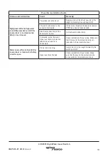
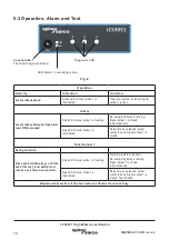
LCS3051 High Water Level Switch
Possible installation faults
Status and indication
Fault
Remedy
Sightglass indicates high water
level (HW) exceeded,red LED for
level probe 1 is not illuminated.
Safety circuit closed.
The probe rod is too short.
Replace probe rod and cut new rod to the
length dictated by the switchpoint HW.
The earth connection to the
vessel is interrupted.
Clean probe threads and ensure excessive
PTFE tape has not been applied.
Electrical conductivity of the
boiler water too low.
Correct water conductivity.
If installed inside the boiler:
Upper vent hole in protection
tube does not exist or is
obstructed.
Check installation of level probe. Make sure
that the level in the protection tube cor-
responds to the actual water level.
Water level sufficient. Red LED for
level probe 1 is illuminated. Safety
circuit is open.
Probe rod is too long.
Cut probe rod to the length dictated by the
switchpoint HW.
Upper vent hole flooded.
Check installation of level probe. Make
sure that the level in the protection tube
corresponds to the actual water level.


