These instructions apply to two different kits:-
ATCU/1 - Spinlock faceplate only.
ATCU/1+ - As above, plus Spinlock handle control lever.
Both kits require installation with an unused Teleflex B700, CH2100P or CH2600P, sourced separately.
Pre Fitment Checks
The throttle body can be mounted vertically or horizontally to suit the installation, with the face plate
remaining vertical. Check carefully in front and behind the surface on which you intend mounting the control
unit. Ensure that the control unit will fit and the cables are able to be lead away without sharp bends that
might affect the operation of the unit. Check the winch handle or Spinlock control lever for un-restricted
travel.
Installation
1) Mark the central position for the control faceplate using the template provided (see transparent sheet) and
mark mounting holes. These consist of four holes Ø5.2mm and one Ø32mm or Ø1 ¼".
It is recommended a 'dry fit' is undertaken before fully sealing and securing the unit.
2) Remove the boss (Item 4) from the faceplate (Item 1), being careful to leave the `o` ring (Item 5) and
backing plate (Item 2) around the boss in place within the faceplate.
Install the boss on the splined shaft of the throttle body. Ensure it is pushed fully to the base.
Sleeve (Item 10) is an optional OEM part which may not be required.
3) Position the face plate and 4 fasteners. Fastener choice (Item 8 or 9) is dependant on your choice of horizontal or
vertical mounting
4) Install the black spacers (Item 7) on the fasteners for either vertical or horizontal mounting. Check
Diagrams 2 & 3.
5) Position throttle body behind faceplate, rotate black spacers (Item 7) to align with throttle body mounts, for
horizontal mounting.
Slide throttle body onto fasteners and loosely tighten nuts or bolt (Item 8A or 9)
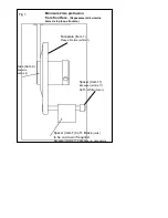
6) Ensure 2mm minimum of boss is protruding from the plate (see Fig 1). The black spacers (Item 7) may need to
be cut down to achieve 2mm protrusion of boss, depending on deck thickness. The spacers can easily be
cut with a hacksaw.
7) Check all operations of the throttle. Neutral throttling, forward and reverse gear selection and in gear
throttle.
Separate the parts ready for final installation.
8) Follow steps above and Diagram 4 to reassemble the unit. Make sure the white mark on the boss is
aligned vertically with the white dot on the faceplate, when the control unit is in the neutral setting.
Use Studlock / Loctite on the three grub screws of the Boss (set screws) and firmly tighten.
9) Before fully tightening the faceplate use silicone sealant, (not a polysulfide or polyurethane sealant) in a
thin bead around the inside edge of the faceplate.
10) Slide the sealing washer (Item 6) over the neutral throttle button.
11) Repeat step 7 and always re-check throttle operation before casting off


