


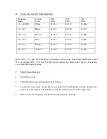


D.
Tuning to Channel Frequencies
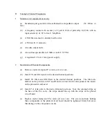
1.
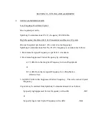
Minimum test equipment necessary
(a) Standard signal generator with a calibrated low impedance output
(50 Ohms or
less)
(b) A frequency counter with accuracy of 1 part in 10(6) or preferably 10(7) Hz with an
input sensitivity of .01 Volts at 1 MegOhm.
(c) A 50 Ohm non-reactive dummy load resistor.
(d) A 500 mA R. F. ammetre.
(e) An audio output metre.
(f)
An oscilloscope useable to 8 MHz or an R.F. VTVM.
(g) A regulated 12 Volt, 2 Amp power supply.
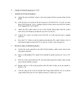
2.
Installation of Channel Components.
(a) Remove crystal clamp and P.A. tank coil cover can.
(b) Install TX and RX crystals in the desired channel positions.
(c) Install TX filters and RX filters in the desired channel positions. The filters are
marked on the pin side with T and R and an arrow which corresponds to the arrows
on the printed circuit board.
(d) Install P.A. tank coils in the desired channel positions. Note the coloured stripe on
the base of the P.A. coils - the stripe should line up with the stripe of the printed
circuit board.
(e) Replace crystal clamp and P.A. tank coil cover can. The screws and nuts holding
these components to the printed circuit board should be tightened firmly but not so
that damage to the components occurs.


