

Your Zone Spot is now connected and ready for
use. For more about connecting readers, inputs
and other deatiled installation instructions, see
the installation Manual.
https://app.doorcloud.com/#/manuals
Login to Door Cloud
using your
username
and
password
.
Go to
Settings > Devices >
Add
to introduce the new
device to the system. Enter
the Name. Select the MAC
address matching the one
from the product label,
either from the device
chasis or packaging box. Set
Type to “Spot”. You can
leave the Area default.
Press Save.
After adding a
freshly installed device you
will be automatically redirected to
device’s general settings view. Now press
Enable (right next to Edit). Activation will
change to
“Enabled”
and a bit later, the
Status will change to
“Online”
. Your device
is now connected to the Door Cloud service.
1 |
2 |
Online
Control Test
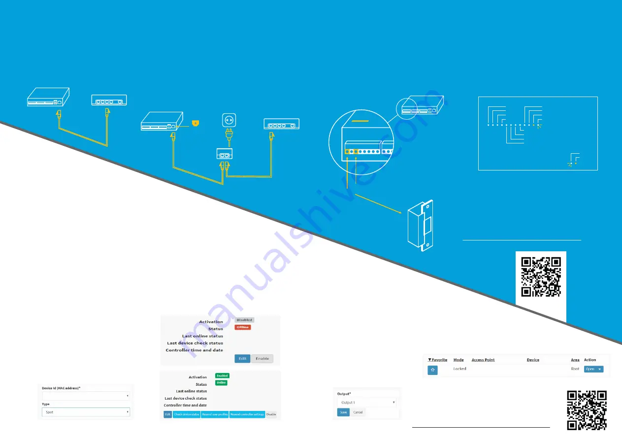
Physical connections
January 2019. All specifications are subject to change without prior notice. © Spica International 2019.
Zone Spot
Ethernet
switch / router
Use a standard ethernet cable
(Cat5e+) to connect Zone Spot
to an ethernet switch.
Look at the Zone Spot faceplate for the PoE
symbol. If you have a PoE model, and your
switch supplies PoE, the power will be
supplied from the switch. If you don’t have
a PoE switch, use PoE injector which is
available in most electronic shops.
3 |
Connect the electrical strike
to OUT1. Choose between
normally open (NO) and
normally closed (NC)
terminal.
4 |
After the power is switched on, the
POWER and ST1 indicators will get
illuminated. Normal controller state is
shown by CPU and ST2 indicators
blinking in a heartbeat manner.
If you cannot see the PoE symbol,
you have the 12V model, so you
will need a power supply of
12V/30W connected to the
+12V and GND pins.
*
Finally you can go to
Monitoring > Live Control
, and
remotely open the door lock by
pressing the
Open
button.
Ethernet
switch / router
AC power
PoE
injector
(optional)
PoE
Zone Spot
*
ZONE SPOT
ZONE SPOT
OUT1
OUT2
OUT3
OUT4
IN3
IN4
IN5
IN6
IN1
IN2
ST1
ST2
CPU
POWER
2 |
3 |
4 |
5 |
1 |
Next, you will
need to configure
the device’s output
OUT1 to control an
access point. Create
a new Access Point
(
Settings > Access
Point > Add
). Select
Output1
from your
new device.
If everything is ok, your lock should react in
about a second or less. For more help, please
check our Getting Started guide at
https://app.doorcloud.com/#/gettingstarted
Zone Spot
ZONE SPOT
NO
NC
ZONE SPOT
OUT1
Electric strike


