SPERONI CS Series Скачать руководство пользователя страница 2

1. General

This manual is meant to provide the user with the
essential information required for installing, using and
servicing the pumps.
A fault-finding chart indicating possible cause and
remedy for every problem which might occur, is
included.

2. Technical characteristics and materials

The electric pumps are the centrifugal, radial, close-
coupled type, with single impeller.
• Cast iron pump-body and support, stainless steel

threaded counter flanges.

•  Stainless steel motor shaft; bronze impeller for the

high head range; cast iron impeller for the low head
range.

•  Mechanical seal housing standardized to DIN 24960.

The mechanical seal is lubricated by the pumped
liquid.

• All the electric pumps come fitted with threaded

counter-flanges.

•  Amply dimensioned ball-bearings pre-packed with

special grease for life.

•  2 pole electric motors of enclosed type, IP 55, with

external ventilation; insulated according to Class F.

•  Standard supply voltages:

50 Hz=230/400 V
up to 7,5 kW - 400/700 V
for higher power ratings.
60 Hz=230/400 V for all powers.
Standard voltage V 230 - 50 Hz.
On request, special voltages available.

• In the standard versions the electric pumps are

suitable for fluid temperatures up to 60°C.

•  Maximum working pressure: 10 Bar.

3. Applications

The electric pumps are suitable for application in the
civil, agricultural and industrial fields, to pump chemi-
cally or mechanically non aggressive liquids. Any
suspended solid particles should not exceed 2% by
weight. The following are but a few typical applications:
water supply systems, irrigation schemes, pressure
tank feed, pressure boosting, air conditioning system,
heating systems.

4. Installation

The pumps may also be located outdoor, provided
they are suitable protected by a roofing; they can also
be installed inclined or vertically.

Warning:

For operation in hot damp environments, the pump
should not be installed orientated to different directions
than normal, to avoid condensation water building up
inside the motor.
Avoid vertical position with motor facing down ward
(see installation diagram - Fig. 5).
Being generously dimensioned, these pumps can be
supported by the pipework of the system to which
they are applied, even though it would be preferable
- where possible - to secure them firmly to a bedplated
by means of four holding-down bolts fitted through
the holes provided in the pump feet. Firm mounting
will aid to damp down vibrations, if any.
A satisfactory installation should conform to the
following indications:
The suction pipe, the inside diameter of which should
never be smaller than the pump inlet, should be
dimensioned consistently with the system and the
pumped liquid. Bear in mind that the maximum theo-
retical suction lift not only is reduced by the NPSHr
required by the pump, which is a peculier characteristic
of the pump itself, but is also reduced by the height
above sea level of the installation and the friction
losses occurring in the suction line.
Therefore, in order to avoid cavitation, which would
generate noise, performance drop and vibrations that
might exert undue mechanicals stress on the pump,
the following relation should always be observed:

hp + hz ≥ (NPSHr + 0.5) + hf + hpv

where:

h

p

is the absolute pressure acting on the free surface of
the liquid in the suction reservoir, expressed in meters
of liquid. hp is the quotient between the barometric
pressure and the specific weight of the liquid.

h

z

is the difference in level between the pump axis and
the free surface of the liquid in the suction reservoir
expressed in metres. hz is negative when the liquid
level is below the pump axis.

h

f

is the head loss occurring within the suction line and
the fittings fitted to it, such as connectors, foot valve,
sluice valves, bens, etc.

2

INSTRUCTIONS FOR THE INSTALLATION AND USE OF ELECTROPUMPS

Содержание CS Series

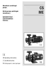
Страница 1: ...ME Monoblock centrifugal pumps Elettropompe centrifughe monoblocco Operating instructions Libretto istruzione Инструкция по зксплуaтaции RUS CS ME CS ...

Страница 2: ...rning For operation in hot damp environments the pump should not be installed orientated to different directions than normal to avoid condensation water building up inside the motor Avoid vertical position with motor facing down ward see installation diagram Fig 5 Being generously dimensioned these pumps can be supported by the pipework of the system to which they are applied even though it would ...

Страница 3: ...ximum permissible suction lift in an installation depends on the value of the atmospheric pressure i e the height above sea level of the installation and the liquid temperature To facilitate the user s task tables are provided which the datum being water at 4 C and at sea level indicate the decrease in the hydraulic pressure head as a function of the height above sea level and the suction losses a...

Страница 4: ...qualize the wear rate of both pumps 4 2 Checking the direction of rotation of the electric pumps with three phase motors The direction of rotation may be checked before the pump is fitted with the liquid to be pumped provided it is run for very brief intervals only The pump must not be run before it is filled with liquid Continuous dry running would damage the mechanical seal beyond repair If the ...

Страница 5: ... is to be modulated proceed as directed under the section installation All pumps which are installed in places unprotected from frost must be emptied whenever they remain inoperative and flushed inside with water emulsified with a corrosion inhibitor 6 Maintenance The electric pumps do not require any scheduled maintenance as the motor bearings are pre packed for life and the mechanical seals are ...

Страница 6: ... F Suction lift too high G Suction pipe too narrow A Fill the pump Prime it again B Repair leaks Fill and prime again C Interchange two supply leads D Replace the pump with a suitable one E Clean foot valve F See section installation G Replace suction pipe with one having diameter larger by 1 4 or 1 2 A Make sure that power supply is connected B Check for any blown fuses C Check for open or dirty ...

Страница 7: ...cordingly If this is not acceptable instal a more powerful motor D Remove cause of harsh rubbing 8 When stopped the pump runs slightly in reverse direction A Leaks or air locks in suction pipe A Correct leaks and read section installation 7 Pump vibrates runs noisily flow rate is uneven A Pump runs beyond rated capacity B Pump or pipework not properly secured C As in 3F D As in 3G A Reduce flow ra...

Страница 8: ...tti da tettoia Oltre che sul piano orizzontale possono essere installate sul piano inclinato e verticale Avvertenza Se l ambiente in cui l elettropompa deve operare è particolarmente caldo e umido si sconsiglia di installare l elettropompa con orientamenti diversi da quello normale per evitare l accumulo di acqua di condensa all interno del motore È da evitarsi la posizione verticale col motore or...

Страница 9: ...re e le perdite d aspirazione in funzione della temperatura Quota sul livello del mare m Perdite di aspirazione in metri 500 0 55 1000 1 1 1500 1 65 2000 2 2 2500 3000 3 3 2 75 21 5 Temperatura acqua C Perdita di aspirazione m 20 0 2 40 0 7 60 2 0 80 5 0 90 7 4 110 15 4 120 Le perdite di carico sono rilevabili dal diagramma riportato sul catalogo e allo scopo di ridurre la loro entità al minimo sp...

Страница 10: ...avoro e una di stand by prevedere anche un interruttore di commutazione tra una pompa e l altra per bilanciare l usura delle pompe 4 2 Controllo del senso di rotazione nelle elettropompe con motore trifase Il controllo del senso di rotazione può essere eseguito prima del riempimento della pompa col liquido da pompare purché essa sia fatta solo per brevi impulsi Non è ammesso il funzionamento della...

Страница 11: ...eriodi con la saracinesca in mandata chiusa Nel caso in cui ciò sia inevitabile e nei casi in cui la portata di mandata debba essere modulata procedere come indicato nel capitolo installazione Le pompe installate in ambienti non protetti dal freddo è necessario svuotarle tutte le volte che rimangono inoperative e lavare l interno con acqua emulsionata con un inibitore di corrosione 6 Manutenzione ...

Страница 12: ...razione con a insufficiente A Riempire la pompa e fare l adescamento B Eliminare la perdita rifare il riempimento e l adescamento C Invertire tra loro due fili di alimentazione D Sostituire la pompa con altra idonea E Disintasare la valvola di fondo F Vedere capitolo installazione G Sostituire il tubo d aspirazione con altro di diametro maggiore di 1 4 o 1 2 A Controllare che vi sia energia elettr...

Страница 13: ... Se ciò non è accettabile occorre richiedere un motore più potente D Eliminare la causa del raschiamento 8 La pompa gira leggermente in senso contrario quando viene fermata A Perdite nella tubazione d aspirazione o sacche d aria nella stessa A Eliminare le perdite e vedere il capitolo installazione 7 La pompa vibra ed ha un funzionamento rumoroso con portata incostante A Funzionamento oltre la por...

Страница 14: ...14 ...

Страница 15: ...15 RUS ...

Страница 16: ...16 ...

Страница 17: ...17 RUS ...

Страница 18: ...18 ...

Страница 19: ...20 RUS ...

Страница 20: ...n nationale prévoit des sanctions à la charge des sujets qui abandonnet ou éliminent les déchets d appareillages électriques ou électroniques de façon illégale SPAÑOL Informaciones sobre el desguace de aparatos eléctricos y electrónicos en conformidad con la directiva 2002 96 CE RAEE Atención no utilizar la normal lata de la basura para desguazar el presente producto Los aparatos eléctricos y elec...

Страница 21: ...lingscenter der har tilladelse til bortskaffelse bedes De kontakte forhandleren hvor produktet er købt Det nationale normativ forskriver sanktioner for dem der foretager ulovlig bortskaffelse eller efterladelse af elektrisk og elektronisk udstyr Tietoja sähköisten ja elektronisten laitteiden hävittämisestä direktiivin 2002 96 EY WEEE mukaisesti Huomio Tätä tuotetta ei saa heittää tavalliseen jätes...

Страница 22: ...NOTE ...

Страница 23: ... EN 292 2 EN 55014 EN ISO 3744 EC declaration of conformity We declare that articles present in this handbook comply with the following Directives 2006 42 CE Curve point at max capacity rated Hz LpA measured 80 dBA R 1m H 1m 2006 95 CE 2004 108 CE 2000 14 CE Pump curve point at max capacity rated Hz LWA measured 94 dBA LWA guaranteeed 95 dBA Procedure followed Enclosure V Applied harmonized standa...

Страница 24: ...Cod 7104529 Rev 3 02 2009 ...

Отзывы: