background image

DF/FF MANUAL                                                                                                          118002-001 R

ev B


Consult Spellman’s Sales Department 
for details. 
 

1.2.2  SYSTEM STATUS AND 

FAULT DIAGNOSTIC 
DISPLAY 

 
Dead front type indicators are provided 
to give the user indication of system 
operation and fault conditions. If a fault 
occurs, the power supply will shut 
down. To reset, toggle the CONTROL 
POWER ON switch, or use the reset 
function on remote user interface. 
 

INTERLOCK CLOSED:

 Indicates 

the EXTERNAL INTERLOCK 
connections are in the closed position. 
 

INTERLOCK OPEN:

 Indicates the 

EXTERNAL INTERLOCK 
connections are in the open position. 
 

OVER VOLTAGE:

 Indicates the over 

voltage protection circuitry has caused 
the power supply to turn off. Over 
voltage is internally set to 105%-110% 
of rated output voltage. 
 

OVER CURRENT:

 Indicates the 

output current has exceeded 10% of 
rated output current. The over current 
level is internally set.  
 

OVER POWER:

 indicates the output 

power has exceeded the front panel or 
remote programmed power trip level. 
 

ARC:

 Indicates that a tube arc has 

occurred. 
 

KV RGLT ERROR:

 Indicates that the 

high voltage regulation circuit cannot 
maintain voltage regulation. This may 
occur if the input voltage is too low. 
 

MA RGLT ERROR:

 Indicates that the 

tube emission current regulation circuit 
error cannot maintain current regulation. 
This may occur when tube filament 
problems exist. 
 

FILAMENT CURRENT LIMIT:


Indicates that filament current has 
exceeded the programmed filament 
current limit trip level. 
 

KV MIN:

 Indicates the minimum KV 

level is not being programmed. This 
indicator will illuminate for 
approximately 10 seconds before shut 
down. This provides protection of the 
tube filament. The KV min circuitry also 
resets the KV and MA/filament ramp 
circuits. When the voltage is programmed 
higher than the kV min level, the outputs 
will begin the ramp cycle. 
 

LEAKAGE LIMIT/TEMP

: On the 

DF/FF power supply, a tube leakage 
current detection circuit is provided. Shut 
down will occur if leakage current 
exceeds 5mA. A test point on the rear 
panel is also provided for test purposes. 
LED LEAKAGE/TEMP will blink at 
approximately 0.5Hz frequency.  
Temperature is constantly monitored 
inside the unit. Shut down will occur if 
temperature exceeds safe operating level. 
Steady illumination on 
LEAKAGE/TEMP front panel LED will 
indicate over temperature condition.  


OPEN FILAMENT:

 Indicates the X-ray 

tube filament or connections to the 
filament are open. 

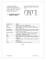
1.3


OPTIONS: 

The options available are listed in Table 
1.1. See Section 5 for more information 
on these options along with operating and 

Содержание X3645

Страница 1: ...DF FF MANUAL 1 118002 001 Rev B ...

Страница 2: ...DF FF MANUAL 2 118002 001 Rev B ...

Страница 3: ...NOID CONTROL SIGNAL 3 2 4 PRINCIPLES OF OPERATION 4 4 1 CHASSIS 4 1 4 2 LINE RECTIFICATION AND FILTERING 4 2 4 3 INVERTER 4 3 4 4 HIGH VOLTAGE TRANSFORMER 4 4 4 5 HIGH VOLTAGE ASSEMBLY 4 5 4 6 FRONT PANEL SYSTEM CONTROL PWB 4 6 4 7 FILAMENT POWER PWB 4 7 4 8 OPTIONS 4 8 5 OPTIONS 5 5 1 208V AC THREE PHASE INPUT 3 PH 5 1 5 2 HIGH STABILITY HS 5 2 5 3 220VAC FAIL SAFE CIRCUIT FSI 220V 5 3 5 4 12VDC ...

Страница 4: ...ltage tube emission current tube filament current limit and maximum tube power are all continuously adjustable via analog remote controls or digitally over RS 232 interface optional The power supplies operate from a variety of line voltages and are fan cooled requiring no water cooling Custom designed units for single use or OEM applications are available 1 2 STANDARD FEATURES The DF FF series inc...

Страница 5: ...TE POWER ON Allows remote control of Control Power ON OFF function This feature also allows remote reset of the power supply in case of a fault shutdown EXTERNAL INTERLOCK Interlock connections are provided for a variety of water flow and safety functions The unit will not operate unless the interlock is closed Opening the interlock circuit will cause the unit to shut off REMOTE STATUS SIGNALS A v...

Страница 6: ...A RGLT ERROR Indicates that the tube emission current regulation circuit error cannot maintain current regulation This may occur when tube filament problems exist FILAMENT CURRENT LIMIT Indicates that filament current has exceeded the programmed filament current limit trip level KV MIN Indicates the minimum KV level is not being programmed This indicator will illuminate for approximately 10 second...

Страница 7: ...ture Coefficient voltage and current FSI 220V Remote Fail Safe circuit operating at 220Vac replaces WFS 220V standard circuit FSI 12VDC Remote Fail Safe circuit operating at 12Vdc 24Vdc standard WFS 24V PO 24Vdc water flow signal switched with power ON switched with X Ray ON is standard WFS 220V PO 220V ac water flow signal switch with power ON switched with X Ray ON standard Not available with FS...

Страница 8: ...chassis for visible damage Fill out and mail the Warranty Registration card accompanying the unit Standard Spellman DF FF High voltage power supplies and components are covered by warranty Custom and special order models with an X suffix in the model number are also covered by warranty 2 2 MECHANICAL INSTALLATION Units in the DF FF series have front panel holes for standard EDI rack mounting The r...

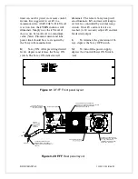
Страница 9: ...TION 5 MINUTES HAVE ELAPSED REMOVE ANY PANELS UNTIL ELECTRICAL SHOCK DO NOT TO REDUCE THE RISK OF JB1 I O XGITF DISCONNECT ALTERNATE USE INTERNALLY FUSED 2 5A X RAY ON LAMP OPTION 220VAC SWITCHED KEEP FAN AND VENT HOLES CLEAR OFF EQUIPMENT AFTER TURNING SERVICING BEFORE POWER DO NOT DISCONNECT CAUTION LINE INPUT CB1 SPELLMAN HIGH VOLTAGE ELECTRONICS CORP HAUPPAUGE NY 11788 MADE IN USA INPUT OUTPUT...

Страница 10: ...D Connect the X ray cable to the X ray tube housing E Connect the X ray cable to the power supply Insure the connector and housing is clean Generally vacuum grease or oil is not required but can be used if desired Tighten the cable collar to the connector housing F Options Note See Section 5 for hook up and operating instructions for the options on your unit Custom models may also require set up c...

Страница 11: ...e 3 1 DF FF Front panel layout HIGH VOLTAGE OUTPUT I H DANGER HIGH VOLTAGE R T O V L G H G N E D A A G E S C L CABLES WHILE POWER IS ON E1 CAUTION 5 MINUTES HAVE ELAPSED REMOVE ANY PANELS UNTIL ELECTRICAL SHOCK DO NOT TO REDUCE THE RISK OF JB1 I O XGITF DISCONNECT ALTERNATE USE INTERNALLY FUSED 2 5A X RAY ON LAMP OPTION 220VAC SWITCHED KEEP FAN AND VENT HOLES CLEAR OFF EQUIPMENT AFTER TURNING SERV...

Страница 12: ...e cover must be on in order to direct the airflow over the areas that need cooling Important In operation the unit must be placed so that the air intake and the fan exhaust are clear of any obstruction that might impede the flow of air 3 2 STANDARD FEATURES A note on remote interface circuitry and remote signal grounding Whenever possible electrical isolation should be provided when interfacing wi...

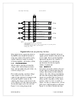
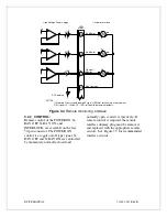
Страница 13: ...llman application engineers are available to assist in interface circuitry design 3 2 1 PROGRAMMING Allows remote adjustment of the tube voltage tube current filament current limit and maximum tube power limit via external voltage source For remote program a positive voltage source from 0 to 10V 0 100 is applied to the appropriate terminals on the rear panel 50 pin D connector By adjusting the vol...

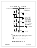
Страница 14: ...ent Figure 3 4 Remote monitoring interface 3 2 3 CONTROL Remote control of the POWER ON X RAY OFF X RAY ON and INTERLOCK are available on the rear 50 pin connector The POWER ON control is a toggle on off type signal X RAY OFF and X RAY ON are controlled by momentary normally closed and normally open contacts respectively If remote control is required the remote interface dummy plug must be removed...

Страница 15: ... 5 X Ray OFF Transistor momentarily for constant X Ray OFF OFF for X Ray OFF or 4 X Ray ON 3 INTLK Closed for INTLK 11 8 RESET ON RESET Momentary transistor Optional Remote Power See Note 1 Customer Supplied 5V Or connect to pin 11 Transistor can be turned off To enable X Ray ON Transistor must be ON ON OFF control and use X Ray OFF for Transistor can be kept ON for toggle operation ON turns X Ray...

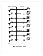
Страница 16: ...rrent limit tube power limit overvoltage filament current limit overtemp leakage current limit and power supply fault is provided These signals are open collector type Normally off and are intended to drive the diode of an opto coupler See Figure 3 6 for recommended interface circuits ...

Страница 17: ...ce High Voltage Power Supply 12 1 4W 100 Ω 470 Ω 5Vdc X Ray ON 100 Ω 1 4W 19 Power Supply Fault 470 Ω 5Vdc 100 Ω 1 4W 16 Filament Current Limit 470 Ω 5Vdc 100 Ω 1 4W 13 Overvoltage 470 Ω 5Vdc 100 Ω 1 4W 15 Overpower 470 Ω 5Vdc 100 Ω 1 4W 17 mA Current Limit 470 Ω 5Vdc 100 Ω 1 4W 14 KV Min 470 Ω 5Vdc Temp 470 Ω 5Vdc 100 Ω 1 4W 21 Figure 3 6 Remote status interface ...

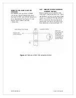
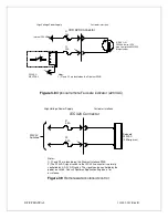
Страница 18: ...3 7 and Figure 3 8 for remote fail safe connections 3 2 5 REMOTE WATER SOLENOID CONTROL SIGNAL Remote signals are provided for tube water flow control and other uses 24V and 220VAC signals are provided These signals are switched ON when X RAY ON is switched on External interlock connections can also be used for water flow interlock as shown in Figure 3 9 Figure 3 7 Remote X RAY ON indicator 24VDC ...

Страница 19: ...Optional remote Fail safe indicator 220VAC High Voltage Power Supply Customer interface Switched 220VAC Solenoid 220VAC 2 0Amp max IEC 320 Connector F1 2 5A 2 5A F2 Notes 1 F1 and F2 are located on the Filament Interface PWB 2 The 220VAC signal switch to the IEC 320 connector is normally controlled by X RAY ON switch The signal can be controlled by the power on switch Consult Spellman Application ...

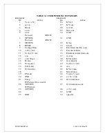
Страница 20: ...OL ref 9 Leakage Mon 34 Pwr limit com OL com 10 24v out 35 Fil current Limit 11 Vcch 5v out 36 Filament current limit com 12 xon 37 mA reg 13 overvoltage 38 KV monitor 14 Kvmin 39 mA monitor 15 Overpower 40 Vcch 5v out 16 Fil I Limit 41 Arc 17 Overcurrent 42 KV ref mon 18 43 MA ref mon 19 PS fault 44 Vcch 5v out 20 GND 45 15v out 21 Temp 46 fil current mon 22 WFS water flow switch OPTION 47 fil cu...

Страница 21: ...onsult IEEE recommended practices for safety in high voltage testing 510 1983 4 1 LINE RECTIFICATION AND FILTERING Basic AC line rectification provides the DC voltage for the high frequency inverter and the filament supply The line input voltage can vary from 180 up to 253 volts within the series In general the following variations can be ordered 200Vac 10 50 60Hz 400Hz three phase or single phase...

Страница 22: ... IGBT gate driver PWB provides the required gate voltages and offsets 4 3 HIGH VOLTAGE TRANSFORMER The output of the High Frequency Quasi resonant Inverter is connected to the primary of the High Voltage Transformer The High Voltage Transformer is a step up type Typical secondary voltages are in the range of 3kV to 16kV depending upon output voltage ratings 4 4 HIGH VOLTAGE ASSEMBLY The High Volta...

Страница 23: ...and open collectors contact 4 6 FILAMENT POWER PWB The filament inverter provides the filament power for the X ray tube The filament inverter is a high frequency series resonant inverter The inverter provides regulated current to the primary of the filament isolation transformer The filament isolation transformer secondary is connected to the output connector For the DC filament option the transfo...

Страница 24: ... switched with POWER ON The standard configuration is switched with X RAY ON 5 6 220VAC WATER FLOW SIGNAL WFS 220V PO 220Vac water flow signal is switched with POWER ON The standard configuration is switched with X RAY ON This option is not available with FSI 220V 5 7 DUAL FILAMENT SUPPLY DFS A dual filament supply is available on DF FF F models only This option allows the DF FF F to power Varian ...

Страница 25: ...FF MANUAL 118002 001 Rev B Spellman welcomes the opportunity to tailor units to fit your requirements or to develop new products for your applications Contact the Spellman Sales Department with your needs ...

Страница 26: ...OUS Only qualified personnel should perform these tests High voltage test procedures are described in Spellman Bulletin STP 783 Standard Test Procedures for High Voltage Power Supplies Copies can be obtained from the Spellman Customer Service Department Test equipment including an oscilloscope a high impedance voltmeter and a high voltage divider such as the Spellman HVD 100 or HVD 200 is needed f...

Страница 27: ...stomer The customer shall pay for shipping to and from Spellman A preliminary estimate for repairs will be given by phone by Customer Service A purchase order for this amount is requested upon issuance of the RMA Number A more detailed estimate will be made when the power supply is received at Spellman Repair Center In the event that repair work is extensive Spellman will call to seek additional a...

Страница 28: ...DF FF MANUAL 118002 001 Rev B ...

Страница 29: ...DF FF MANUAL 118002 001 Rev B ...

Страница 30: ...DF FF MANUAL 118002 001 Rev B ...

Страница 31: ...DF FF MANUAL 118002 001 Rev B ...

Страница 32: ...DF FF MANUAL 118002 001 Rev B ...

Страница 33: ...DF FF MANUAL 118002 001 Rev B ...

Страница 34: ...DF FF MANUAL 118002 001 Rev B ...

Страница 35: ...DF FF MANUAL 118002 001 Rev B ...

Страница 36: ...DF FF MANUAL 118002 001 Rev B ...

Страница 37: ...DF FF MANUAL 118002 001 Rev B ...

Страница 38: ...DF FF MANUAL 118002 001 Rev B ...

Страница 39: ...DF FF MANUAL 118002 001 Rev B ...

Страница 40: ...DF FF MANUAL 118002 001 Rev B ...

Отзывы: