8 |
P a g e
8
DESCRIPTION & OPERATION
SECTION 1 Instruction Manual
INSTALLATION
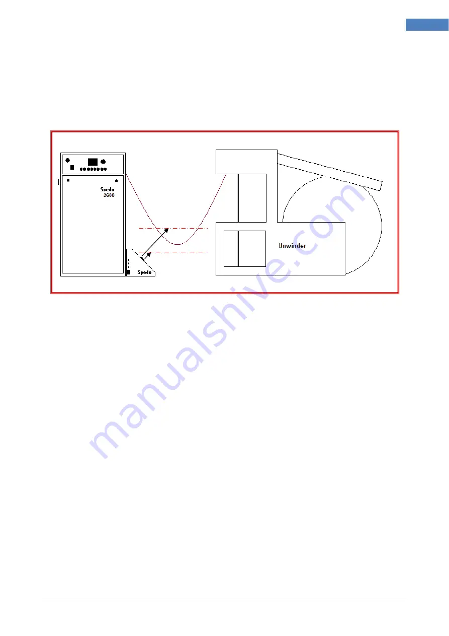
Position optical loop box in front of the cutter so that both sensors are aligned with the
paper web.
Ensure all cables are fitted to the corresponding plugs and tighten into position.
Fig 1.3 Operating States
Switch on the forms cutter. Check that the optical loop interface unit is now powered up and
the ADEV RUN and the ADEV READY indicators are illuminated.
Place a piece of paper in front of the cutter control sensor and check that, at a maximum of
300 mm, the CUTTER RUN indicator toggles on and off as the paper is moved inside and
outside the sensing range.
Place a piece of paper in front of the printer control sensor and check that, at a maximum of
100mm the ADEV RUN indicator toggles on and off. Note: this output is on a time delay of
approximately 2 seconds. This time delay can be adjusted as required. (see page 9).
If the above check is satisfactory, the unit is ready to operate.


