background image

InVision Nano Table Installation only

0118583R4 Page 4 of 4


925 FIRST AVENUE, CHIPPEWA FALLS, WI 54729  /  800-235-1262  /  715-723-6750  /  WWW.SPECTRUMFURNITURE.COM

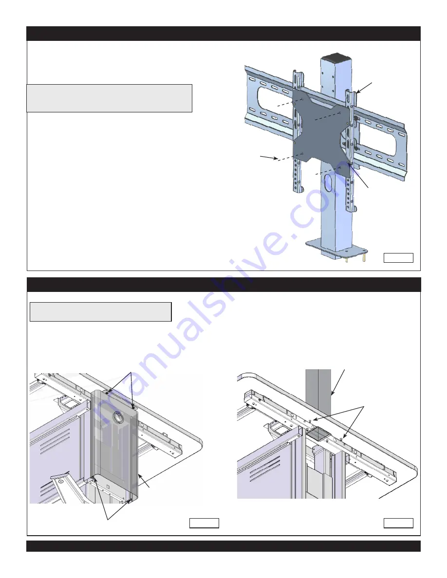
1.  Remove the (4) screws shown.  

Figure 7.1

.

2.  Remove end panel.

Figure 7.1

End panel

Remove these screws

Remove these 

screws

Note: To install the Display Stand on a Nano table, 

the end panel must be removed prior to installing.

1/4-20 Flanged 

serrated locknut

(4 required)

3.  Align the studs and insert the upright into the worksurface 

mounting holes.

4.  With a second person holding the upright, install the (2) inner 

1/4-20 Flanged serrated locknuts.  

Figure 7.2

.

5.  Replace the end panel. 

6. 

Install the (2) outer 1/4-20 flanged serrated locknuts.

7.  Tighten all locknuts securely.

Figure 7.2

Upright assembly

200mm VESA adapter plate (optional)

Attach 200mm VESA 

monitor using these 

(4) holes

Hanging rail

(4) 1/4-20 Keps 

nuts to secure

200mm VESA


adapter plate

Figure 6

Note: The included adapter plate is for 200mm VESA monitor 

applications.  To install, align the adapter plate posts with the 

hanging rail mounts and secure with 1/4-20 Keps nuts.

Содержание 37130

Страница 1: ...35 1262 715 723 6750 Thank you for purchasing Spectrum products Display Stand 37130 4mm Hex wrench included Tools Required 1 0119747 Monitor mount 4 0108896 1 4 20 Flanged serrated locknut 12 052605 1 4 20 x 15mm JC bolt 1 0118193 End cap 3 x 3 1 0118510 Upright assembly 1 0131924 Upright bracket Figure 1 Rubber thread protectors Bottom of upright assembly 7 16 or Adjustable wrench 1 025039 4mm He...

Страница 2: ...ll facilitate installation of the display stand fasteners If attached remove the worksurface fasteners securing it to the base and slide the worksurface 6 over the base to provide access to the display stand mounting holes Figure 3 4 Align the studs and insert the upright into the worksurface mounting holes 5 With a second person holding the upright Install 4 1 4 20 Flanged serrated locknuts and t...

Страница 3: ...g 4 1 4 20 x 15mm JC bolts and tighten securely Multiple mounting holes height positions are available on the upright assembly Figure 4 7 Refer to the instructions included with the monitor mount for complete monitor installation procedure 8 Install the monitor mounting plate to the upright bracket with 4 1 4 20 x 15mm JC bolts and tighten securely Figure 5 9 Install monitor and route wiring throu...

Страница 4: ...and insert the upright into the worksurface mounting holes 4 With a second person holding the upright install the 2 inner 1 4 20 Flanged serrated locknuts Figure 7 2 5 Replace the end panel 6 Install the 2 outer 1 4 20 flanged serrated locknuts 7 Tighten all locknuts securely Figure 7 2 Upright assembly 200mm VESA adapter plate optional Attach 200mm VESA monitor using these 4 holes Hanging rail 4 ...

Отзывы: