background image

SpectraPure®Inc

 Fax  480.894.6109 Fax us toll-free 1.877.527.7873

E-mail: [email protected] Visit us on the web www.spectrapure.com

5

SpectraPure

®

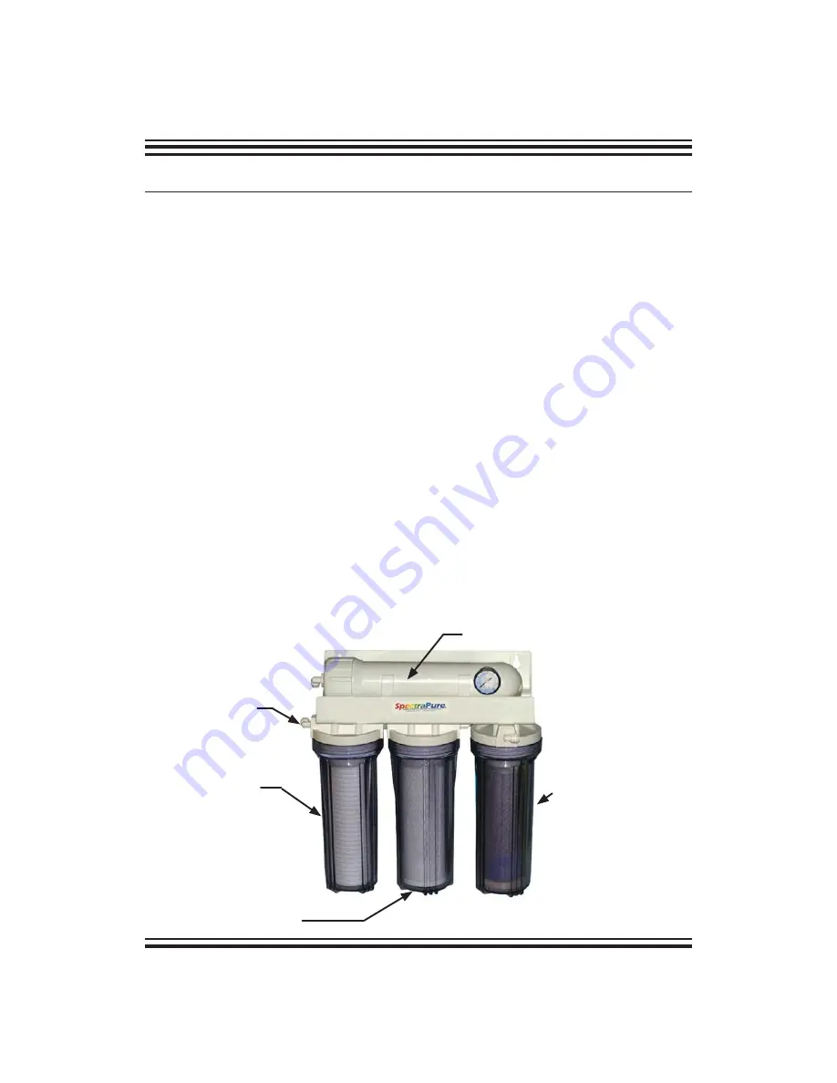
The SpectraPure MPDI system is a four stage reverse osmosis de-ionization system.


1. 

First, the incoming feed water is passed through a 1 micron Micro-Tec™ sediment 


pre-filter. This filter is required to remove excess turbidity (particulate matter) that may


 cause the membrane to plug. 

2. 

The second stage of filtration is a 1 micron carbon block pre-filter. This filter removes 


organics and chlorine from the feed water that can damage the membrane. 


(9,000 gal of Chlorine removal)

3. 

The third filtration stage of the system is a high rejection,  thin film composite


(TFC) reverse osmosis membrane. It removes over 95% of most inorganic salts, all 


micro-organisms and almost all high molecular weight organics in the water. 

4. 

The fourth stage moves water through a Mixed-Bed Multi-Layer Deionization 


Cartridge. Mixed-Bed Multi-Layer Deionization Cartridges are fabricated 


with color-indicating resins for highest possible purity water. They are capable


of producing 18 meg-ohm-cm resistivity water. They are the first DI cartridges


designed to reduce silica, nitrates and phosphate levels in the low ppb range. These


newly formulated cartridges far exceed the  performance of previous cartridges, 


offering enhanced contaminant removal, longer life and higher purity.

Caution: The deionization cartridge life is greatly reduced when operated on low pH 
waters, or water with high CO2 (carbon dioxide) levels.

 The exact cartridge life will vary 

greatly with pH, carbon dioxide levels, and TDS etc. in your RO water or the feed water
supplying the RO system. Aeration or de-gassification of RO product water is recommended 
for such waters for removal of carbon dioxide.

TFC RO Membrane

(MEM-00xx) - (inside housing)

DI Cartridge

(DI-SB-CI-10)

Sediment Filter

(SF-MT-0.5-10)

Carbon Block

(CF-0.5-10)

IN Port

SYSTEM DESCRIPTION:

Содержание MaxPure MPDI DI System

Страница 1: ...roceeding with installation Failure to follow any attached instructions or operating parameter may lead to the product s failure and possible damage to property Reverse Osmosis Ion Exchange Water Purification System Single and Dual Membrane Models INSTALLATION AND OPERATING MANUAL ...

Страница 2: ...ent 10 11 Filter Diagnostics Sediment Filter Diagnostic 12 Carbon Filter Diagnostic 13 Deionization Cartridge Diagnostic 14 RO Membrane Diagnostic 15 17 Troubleshooting Guide Troubleshooting Guide for the System 18 Troubleshooting the RO Membrane 19 21 Tips Storage 22 Replacement Optional Parts 24 COPYRIGHT 2002 2009 BY SPECTRAPURE INC ALL RIGHTS RESERVED TABLE OF CONTENTS Thank You for your purch...

Страница 3: ...ce of tested SpectraSelect RO membrane elements only for one year from date of receipt by the buyer providing that the loss of performance was not caused by fouling neglect or water conditions exceeding the feed water parameters listed in the applicable product manual refer to detailed membrane warranty information SpectraPure will on confirmation of loss of performance during the warranty period ...

Страница 4: ...ml min 90 340 235ml min 940 ml min 180 680 470ml min 1880 ml min Reverse Osmosis Membrane Feed Water Requirements For the 1 year SpectraSelect TFC membrane pro rated warranty to be honored the following conditions must be met Operating Pressure 40 80 psi 2 75 5 5 bar pH Range 3 11 Maximum Temperature 100 F 38 C Maximum Turbidity 1 0 NTU Maximum Silt Density Index 5 0 based on 15 min test time Maxi...

Страница 5: ... fourth stage moves water through a Mixed Bed Multi Layer Deionization Cartridge Mixed Bed Multi Layer Deionization Cartridges are fabricated with color indicating resins for highest possible purity water They are capable of producing 18 meg ohm cm resistivity water They are the first DI cartridges designed to reduce silica nitrates and phosphate levels in the low ppb range These newly formulated ...

Страница 6: ...urified water tubing Membrane 2 concentrate push fitting yellow concen trate tubing Membrane 1 feed push fitting black membrane feed tubing mounting bracket Membrane 1 Membrane 2 product water tee carbon filter output push fitting blue product water interconnect tubing Membrane 2 feed push fitting black interconnect feed tubing Membrane 1 concen trate push fitting Membrane 1 prod uct water push fi...

Страница 7: ...ack tubing to your cold water source Never run hot water greater than 100 F 38 C through the system 2 Place the yellow concentrate waste tubing and the blue purified product water tubing into a drain Do not restrict flow from these lines 3 Open the cold water supply valve You may use pressure up to 80 psi 5 5 bar Check the system to ensure that all fittings are tight and leak free before leaving t...

Страница 8: ...m of 4X the product flow rate 4X to 6X is an acceptable concentrate flow rate Procedure 1 Collect product water blue tubing into a measuring cup for one minute Measure the collected amount in milli liters Do the same with the wastewater yellow tubing WASTE YELLOW IN MILLILITERS______________ DIVIDED BY PRODUCT BLUE IN MILLILITERS______________ The resultant is the Concentrate to Product Ratio Alth...

Страница 9: ...2 7 175 67 6 15 2 164 62 7 17 8 154 58 8 20 3 148 56 9 22 9 141 54 10 25 4 136 52 11 27 9 133 50 12 30 5 129 49 13 33 0 128 48 14 35 6 124 47 15 38 1 124 47 16 40 6 PRODUCT RATE CUT TO LENGTH FR 60 ml min gpd in cm 158 60 1 2 5 130 49 2 5 1 123 47 3 7 6 110 42 4 10 2 99 38 5 12 7 94 36 6 15 2 93 35 7 17 8 88 33 8 20 3 84 32 9 22 9 79 30 10 25 4 76 29 11 27 9 74 28 12 30 5 71 27 13 33 0 68 26 14 35...

Страница 10: ...flow restrictor insert from the end of the tubing The entire flow restrictor consisting of the insert collar and thin capillary tubing may then be gently extracted Note Take care not to crush or otherwise damage the delicate capillary tubing 3 Refer to the Flow Restrictor Tables Fig D Find the table that represents the Flow Restrictor Assembly for the system that you have Find the product flow rat...

Страница 11: ...ance is felt approximately 1 2 inch 12 7 mm The tubing is now resting on the O ring seal inside the fitting c Firmly push the tubing approximately an additional 1 4 inch 6 35 mm further into the fitting to completely seat the line into the fitting and O ring seal 7 Turn on the system water supply and check for leaks prior to further use or testing If a leak is observed you may not have pushed the ...

Страница 12: ... will need to be replaced If you remove the sediment and the pressure does not return to normal the carbon filter may be plugged Sediment Pre Filter Replacement Materials Required 0 5 micron MicroTec Sediment Filter SF MT 0 5 10 Filter Wrench Procedure 1 Turn off water supply to the system 2 Using the provided filter housing wrench remove the first housing on the left Unscrew it counterclockwise a...

Страница 13: ...contaminants but a carbon filter can also drop production if its covered with extremely fine sediment If the carbon becomes plugged with sediment it will no longer be able to remove chlorine Carbon Block Filter Replacement Materials Required 0 5 micron Carbon Block Filter CF 0 5 10 Filter Wrench Chlorine Test Kit TK CL 25 Procedure 1 Turn off water supply to the system 2 Using the provided filter ...

Страница 14: ...ter wrench Procedure 1 Remove the filter housing from its cap by unscrewing it counter clockwise as viewed from the bottom 2 Remove and discard the old cartridge from the housing 3 Thoroughly wash out the housings with hot soapy water to which a few teaspoons of household bleach have been added Rinse well with clean hot water 4 Install the new deionization cartridge Make sure the cartridge is inst...

Страница 15: ...our RO water purity See page 10 for removal of push fittings on tee RO WATER TDS READING _______________ 3 Once you obtain the RO water TDS reading reconnect the blue line back to its original location 4 Now test the quality of the TAP water TAP WATER TDS READING _______________ 7 Follow the calculation located on pages 19 20 to determine your membranes impurity rejection Note All water sources ar...

Страница 16: ... This may require two people 5 Use a pair of pliers to grasp the membrane stem and pull the membrane from the housing Fig F 6 Remove the black housing O ring Fig F Wash the empty housing with soapy water Rinse thoroughly with hot clean water 7 Insert new membrane into the housing with the double O ring end first Fig G The tube must fit into the recess at the bottom of the membrane housing When the...

Страница 17: ...ect the yellow concentrate tubing page 10 from the membrane housing Remove and discard the flow restrictor Fig E 2 Reconnect yellow concentrate tubing back to the membrane housing and run water through system for at least 2 gallons This step will flush out membrane preservatives 3 Disconnect the yellow tubing again and insert the new flow restrictor Follow procedure on page 8 9 for measuring waste...

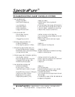
Страница 18: ...ressure reducing valve 4 Red light on purity monitor comes on a Exhausted deionization cartridge i Replace cartridge b Bad membrane exhausted cartridge ii Replace membrane deionization cartridge c Faulty monitor probe iii Replace monitor probe 5 Pressure gauge does not register anything a Missing flow restrictor i Put flow restrictor in the yellow line b Pressure gauge screwed in too far ii Unscre...

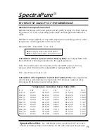
Страница 19: ...lied pressure Note The membrane is rated to produce the rated GPD at 60 psi For any pressure other than 60 psi the output GPD is multipled by the PCF PCF Line Pressure in psi 60 Calculation of Temperature Correction Factor TCF The output GPD also decreases with decrease in temperature This is because water viscosity increases with decrease in water temperature Temperature Correction Factor Table T...

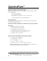
Страница 20: ...r TDS Total Dissolved Solids Important Test the quality of the membrane once every 6 months Procedure 1 Measure tap water TDS Call it X 2 Run the system for 15 20 minutes 3 Measure RO water s TDS Call it Y 4 Subtract RO water TDS from tap water TDS X Y 5 Divide this quantity by tap water TDS X Y X 6 Rejection X Y X 100 Rejection of the RO Membrane Calculation Example 1 Tap water TDS 150 ppm X 2 RO...

Страница 21: ... Membrane Conductivity RO product water TDS greater than Yes Membrane OK Tester Conductivity 95 Alkalinity Measure feed water and Is Rejection No Replace Membrane Test Kit RO product water greater than Yes Membrane OK Alkalinity 90 Hardness Measure feed water Is Rejection No Replace Membrane Test Kit and RO product water greater than Yes Membrane OK Hardness 90 Caution This test is not to be used ...

Страница 22: ...ng reverse osmosis systems on softened feed water greatly reduces the chances of membrane fouling 1 It is recommended that you store your RO System in a cool place when not being used 2 If your system is exposed to sunlight you will grow algae in the housing and it may damage your system 3 Your RO System must be protected from freezing or temperatures above 100 F 38 C 4 MEMBRANE WARNING All Spectr...

Страница 23: ...SpectraPure Inc Fax 480 894 6109 Fax us toll free 1 877 527 7873 E mail spectra spectrapure com Visit us on the web www spectrapure com 23 SpectraPure ...

Страница 24: ...strictor for 60 gpd 228 lpd System FR 90 Flow Restrictor for 90 gpd 340 lpd System FR 180 Flow Restrictor for 180 gpd 680 lpd System DI SB CI 10 Color Indicating SilicaBuster Mixed Bed DI Cartridge GHA 4 1 4 6 35 mm Garden Hose Adapter WR UNIV Filter Wrench Optional Accessories Model Optional Part FAU SMP Quick Connect Faucet Coupler DM 1 Dual probe Inline TDS Meter COM 100 Hand held TDS Conductiv...

Отзывы: