background image

O

O

2

2

F

F

B

B

3

3

M

M


U

U

s

s

e

e

r

r

s

s


G

G

u

u

i

i

d

d

e

e


            Rev.1.0 (Dec. 2015) 

4


Contents 

1.


Introduction .................................................................................................................................................... 5


1.1.


Overview ............................................................................................................................................... 5


1.2.


Specifications ........................................................................................................................................ 6


2.


Product Description ...................................................................................................................................... 8


2.1.


Contents ................................................................................................................................................ 8


2.2.


Product Preview .................................................................................................................................... 8


2.3.


Physical description .............................................................................................................................. 9


2.3.1.


External View .............................................................................................................................. 9


2.3.2.


Dimensions ................................................................................................................................. 9


2.3.3.


External Connector ................................................................................................................... 10


2.3.4.


Factory Default Switch .............................................................................................................. 10


2.4.


Functional Description ........................................................................................................................ 11


3.


On Site Installation ...................................................................................................................................... 13


4.


Getting Started ............................................................................................................................................. 14


4.1.


PC Requirement ................................................................................................................................. 14


4.2.


Quick Installation Guide ...................................................................................................................... 15


4.2.1.


Connect PC and O2FB3M to network. ..................................................................................... 15


4.2.2.


Set IP parameters on O2FB3M ................................................................................................ 15


4.2.3.


Remote video connection to O2FB3M...................................................................................... 16


4.2.4.


Additional settings through connection to the Admin Page ...................................................... 18


5.


Troubleshooting ........................................................................................................................................... 19


5.1.


No power is applied ............................................................................................................................ 19


5.2.


Cannot connect to the Video ............................................................................................................... 20


5.3.


Technical Assistance ........................................................................................................................... 21


Appendix A – Important Notice in Exchanging SD Card (Micro SD) ......................................................................... 22


Содержание O2FB3M

Страница 1: ...O2 Flexible Intensifier Technology 1080p Bullet IP Camera O2FB3M Flexible Intensifier Technology IP Camera with Motorized Lens with Motorized Lens ...

Страница 2: ...ry to correct the interference by one or more of the following measures Reorient or relocate the receiving antenna Increase the separation between the equipment and receiver Connect the equipment into and outlet on a circuit different from that to which the receiver is connected Consult the dealer or an experienced radio TV technician for help Directions Be careful not to cause any physical damage...

Страница 3: ...O O2 2F FB B3 3M M U Us se er r s s G Gu ui id de e Rev 1 0 Dec 2015 3 Revision History Date Revision Details 12 15 2015 1 0 Initial version ...

Страница 4: ...fault Switch 10 2 4 Functional Description 11 3 On Site Installation 13 4 Getting Started 14 4 1 PC Requirement 14 4 2 Quick Installation Guide 15 4 2 1 Connect PC and O2FB3M to network 15 4 2 2 Set IP parameters on O2FB3M 15 4 2 3 Remote video connection to O2FB3M 16 4 2 4 Additional settings through connection to the Admin Page 18 5 Troubleshooting 19 5 1 No power is applied 19 5 2 Cannot connec...

Страница 5: ...e most optimized solution to handle any lighting condition to fit the installation environment Intensifier mode can be used to display a color image in low light In extreme darkness adaptive super IR LEDs can be used to illuminate the scene without IR saturation of the scene Lastly when a monochrome image is desired without the assistance of IR LEDs a clear image can be captured with just a little...

Страница 6: ... Programmable Zones Motion Detection ON OFF 4 Programmable Zones Digital Zoom 1x 12x Mirror H V Rotate DEFOG ON OFF OSD BUILT IN Heater Yes IR range 98 ft depending on scene reflection Video Compression method Simultaneous Dual Codec H 264 MJPEG Resolution 1 920 x 1 080 30fps Multi Profile Streaming 5 simultaneous video profiles Select the codec type resolution and frame rates for each profile Int...

Страница 7: ...o MDIX Analog output 1 channel D1 CVBS output Alarm input output Alarm I O 1 Sensor input 1 Relay output Factory Reset Supported Audio MIC Line in Line out Power DC 12V input Alternate Power Standard PoE IEEE802 3af Alarm Event Intelligent Video Motion Detection Alarm Triggers Motion Detection Sensor Input Alarm Events Video file upload FTP Still Image transmission Email Relay output Alarm Buffer ...

Страница 8: ...Software User s Guide Reference Guide Quick installation guide 2 2 Product Preview O2FB3M Camera Unit PC software to allocate an IP address to the IP Camera the following Description Remarks O2FB3M main unit Screws 2 type type wrench 2 type CVBS Cable Software User s Guide Quick installation guide Guide pattern ONSIP Installer PC software to allocate an IP address to the IP Camera Remarks ...

Страница 9: ...O O2 2F FB B3 3M M U Us se er r s s G Gu ui id de e Rev 1 0 Dec 2015 9 2 3 Physical description 2 3 1 External View Figure 2 1 External view of O2FB3M 2 3 2 Dimensions Figure 2 2 Dimensions Unit mm ...

Страница 10: ...he camera There are two functions assigned to factory default switch 1 Returning to Factory Default State Press the switch about 5 seconds while power is applied to return to factory default state 2 Safe Removal of Micro SD Card Press the switch for 1 second to unmount the Micro SD Card for safe removal Figure 2 4 Factory Default switch and Micro SD Card slot Video Output CVBS Factory Default Swit...

Страница 11: ... is output through Line out in bi audio mode Power input for supplying 12V DC power O2FB3M is powered by PoE do not plug in DC Jack with active DC power into DC power connector 45 with standard PoE IEEE 802 3af Please insert SD memory card when you want to use SD memory card In case of pulling out SD memory Connect external audio source or microphone Connect speakers with built in amplifier Audio ...

Страница 12: ...s light Relay is normal open and it will be closed upon alarm annunciation or remote on The relay is capable of switching 30V AC DC 2A For the application which needs power switching beyond this limit use additional relay switch as shown in the right of Figure Left switching requirement below 30V 2A Right switching requirement higher than 30V 2A Apply this connection when either voltage or current...

Страница 13: ...uld be paid during the installation so that no moisture is allowed to penetrate into the unit through the cables or conduits during the lifetime of the product Products where the internal parts are exposed to moisture because of improper installation are not covered by warranty 1 Fix the base on a flat surface 2 Adjust the rotational position of the camera for desired viewing of the site ...

Страница 14: ...n a PC running client programs Minimum requirement of the PC is described below ITEM Minimum Requirement Recommended Specification CPU Intel Core i3 3Ghz Intel Core i7 Main Memory 2GB 4GB Operating System Windows XP Windows 7 64bit Web Browser Internet Explorer 8 9 Internet Explorer 8 9 Graphic Card Video RAM 256MB Resolution 1920x1080 Video RAM 1GB Higher than 1920x1080 Network 10 Base T Ethernet...

Страница 15: ...gs iv You can connect to admin page by clicking on 10 to network Prepare a PC to run programs for the installation and video connection PC is needed to assign IP address to O2FB3M In the case of using PoE connect the PC and O2FB3M to the network using one of the following ways If your LAN Switch does not support standard PoE connect O2FB3M as shown in dotted line in Figure The DC power is applied ...

Страница 16: ...nd rearranging the list Select network mode that best suits from the drop down list in 5 You can choose either Static or respectively If ADSL and Auto are selected the fields in 6 In case of ADSL fill the User Name and Password in 8 with the values provided by your ISP If DDNS service is needed check the box and fill the empty field with the hostna O2FB3M Web Viewer offers simplest way of video co...

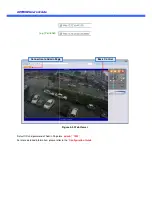
Страница 17: ...in Page are For more detailed information please refer to the Connection to Admin Page e g Port 8080 Figure 4 3 Web Viewer Default ID and password of Admin Page are admin 1234 For more detailed information please refer to the Configuration Guide Connection to Admin Page Basic Control ...

Страница 18: ...isticated target application parameters need to be changed through the admin page The admin page can be connected through http IP_Address Port_Number admin htm ID and password of the administrator are required Default ID and password are admin 1234 It is highly recommended to change the ID and password to prevent illegal access to the IP camera For more detailed information Please refer to the Con...

Страница 19: ...uct 2 The LAN switch supports standard PoE Make sure that both the IP camera and the LAN switch support standard PoE IEEE 802 3af In case of DC adapter If PoE is not applied the power and network connection should be made through separate cables It is recommended to use DC adapter supplied by provider for the feeding of the power In case of replacing the DC power supply make sure that the power su...

Страница 20: ...n Cmd Ping IP address Ex Ping 172 16 42 51 If Reply from message is returned in the figure below the network connection is in normal state Try connection to the video again If the problem persists or refer to other trouble shooting notes If Request timed out message is returned in the figure below the network connection or network setting is not in normal state Check the network cable and settings...

Страница 21: ...ing information 1 1 1 1 Model name 2 2 2 2 MAC address and Registration number 3 3 3 3 Purchase date 4 4 4 4 Description of the problem 5 5 5 5 Error message If you need any technical assistance please contact technical support For immediate service please MAC address and Registration number Description of the problem For immediate service please ...

Страница 22: ...the SD Card 1 Press factory default button for 1 sec to unmount the SD Card SD Card can also be unmounted by going to Admin Page Sensor Capture Setup and clicking on CONFIRM button at the right of SD Card Unmount menu 2 Unplug the SD Card If no action is taken within 1 minute SD Card will be mounted again 3 Plug in new SD Card 4 If the SD Card is a new one for the IP camera format the SD Card by f...

Отзывы: