12
Helpline No: UK 0151 649 1500 / IRE 189 094 6244
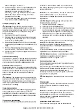
2. Layout (Fig. 1)
1. Chain
bar
2. Saw
chain
3. Chain tensioning screw
4. Stop
claw
5. Chain brake lever / front hand
guard
6. Front
handle
7. Starter
handle
8.
Spark plug (under the air filter cover)
9. Air filter cover
10. Stop switch
11. Safety lock
12. Oil tank cap
13. Fan housing
14. Fuel tank cap
15. Rear handle / bootstrap
16. Chain guard
17. Choke / (carburetor setting)
18. Bar fastening nut
19. Throttle lever
20. Chain catch
Safety features (Fig.1)
2
LOW KICKBACK SAW CHAIN helps significantly
reduce kickback, or the intensity of kickback, due
to specially designed depth gauges and guard
links.
5
CHAIN BRAKE LEVER / HAND GUARD protects
the operator’s left hand in the event it slips off the
front handle while saw is running.
5
CHAIN BRAKE is a safety feature designed to
reduce the possibility of injury due to kickback by
stopping a moving saw chain in milliseconds. It is
activated by the CHAIN BRAKE lever.
10
STOP SWITCH immediately stops the engine
when tripped. Stop switch must be pushed to ON
position to start or restart engine.
11
SAFETY TRIGGER prevents accidental
acceleration of the engine. Throttle trigger (19)
cannot be squeezed unless the safety latch is
depressed.
20
CHAIN CATCHER reduces the danger of injury in
the event saw chain breaks or derails during
operation. The chain catcher is designed to
intercept a whipping chain.
Note:
Study your saw and be familiar with its parts.
3. Proper use
The chain is designed exclusively for sawing wood.
You may only fell trees if you have received the
appropriate training. The manufacturer cannot be
held liable for damage caused by improper or
incorrect usage.
Please note that our equipment has not been
designed for use in commercial, trade or industrial
applications. Our warranty will be voided if the
machine is used in commercial, trade or industrial
businesses or for equivalent purposes.
4. Environmental protection
Dispose of soiled maintenance material and
operating materials at the appropriate collection
point.
Recycle packaging material, metal and plastics.
5. Installation
Important:
Do not start the engine until the saw
is fully assembled.
Important:
Wear protective gloves at all times
when handling the chain.
5.1 Fit the chain bar
To ensure that the bar and the chain are supplied
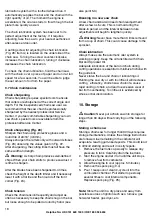
with oil, USE ONLY THE ORIGINAL BAR. The oiling
hole (Fig. 2/Item A) must be kept clear of dirt and any
build-up of residue.
1.
Make sure the Chain brake lever is pulled back
into the DISENGAGED position (Fig. 3A)
2.
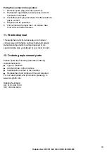
Remove the two bar fastening nuts (B). Remove
the cover (Fig. 3B).
Important:
When assembling for the first time,
the material fitted to provide protection during
transportation (Fig. 3C/Item 24) must be removed
first.
3.
Using a screwdriver, run the adjustment screw
(D) COUNTERCLOCKWISE until the TANG (E)
(projecting prong) is to the end of its travel toward
the clutch drum and sprocket (Fig. 3C).
4.
Fit the open end of the chain bar over the die bar
pins (F) (Fig. 3D).
5.2 To install saw chain
1.
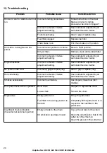
Spread chain out in a loop with cutting edges (A)
pointing CLOCKWISE around loop (Fig. 4A).
2.
Slip the chain around the sprocket (B) behind the
clutch (C). Make sure the links fit between the
sprocket teeth (Fig. 4B).
3.
Guide the drive links into the groove (D) and


