51.
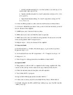
The value of 0XF9 in the configuration file must read 01 41 24 11 to enable
96Khz operation. Xf5 and Xf7 should have values 00 04 04 04.
52.
Select “BQ12” on the flow chart.
53.
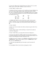
Pull down Ch1 drop down menu, select wipe.EQ310X and press ENTER. You
must do this before loading an EQ310X file to wipe out the previous settings.
Now select your LF.EQ310 file and press the ENTER button. Repeat for channels
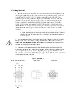
2 and 3 using the filters appropriate for the channel. Default Channel assignments
in the DSP architecture are:
LF
MF
HF
SP1
Ch3
na
na
SP2 Ch3
Ch1
SP3 Ch3
Ch2
Ch1
54.
IMPORTANT NOTE: On the front panel mute switches and the speaker
connector, channels 1 and 3 are reversed from the DSP internal labeling. 1 is 3
and 3 is 1. Or to put it another way, To the outside world ch1 is LF and Ch3 is
HF.
55.
Select ‘PAGE 2”
56.
Select “Vol”. Set the volume offset between channels using the sliders. Close
the dialog box.
57.
Select “Delay3” button. Add desired delay to channels. Each increment is
10.4uS. Close dialog box.
58.
Select “SAVE” Enter a new unique file name for this configuration.
59.
You may now unmute the amplifier and measure the response. Volume may
be readjusted with the mute removed, but filters should be loaded with mute on in
order to avoid sending pops and clicks through the system.
60.
When the program is complete, select EEPROM on the EQ GUI panel. Select
“EEPROM Write”. After several seconds you will see “EEPROM Done” Click
OK and close the EEPROM panel.
61.
Turn off the SP amplifier. Remove the interface cable. Turn on the SP
amplifier.
62.
The amplifier will now turn on with your program every time.


