Spartus EasyMIG 220E PULSE SYNERGY Скачать руководство пользователя страница 7

In case of doubt, checks by an expert should 
be made to establish noise levels in any 
particular environment, and, if these are 
in excess of the prescribed limit, one of the 
following alternatives may apply: 
a) Insulation of the noise source as far as 
possible, e.g. by 

fi

 tting silencers or sound 

proof enclosures
b) Insulation of the operator from the noise 
source
c) E

 ective maintenance of sound protection 

devices
d) Indication as „ear protection areas” where 
applicable
e) Restriction of entry to these „ear protection 
areas” to authorized persons.
f) Protect your hearing with appropriate 
personal protection measures, e.g. earplugs 
or hearing protectors.

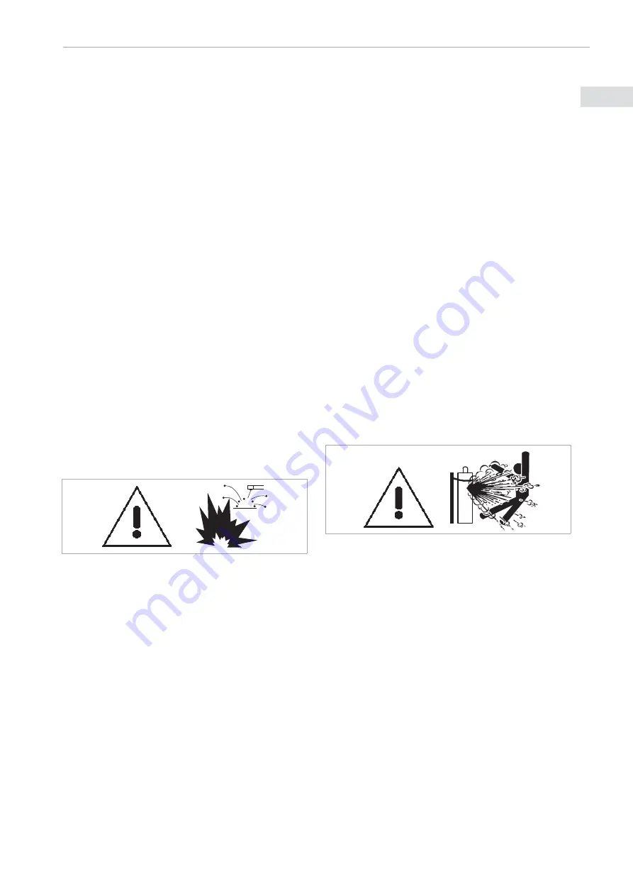
1.6. FIRE AND EXPLOSION

Arc welding and allied processes can cause 

fi

 re and explosions and precautions should 

be taken to prevent these hazards. 

1.6.1. FIRE


• 

Before setting to perform welding 
operations, ensure that elements involving 

fi

 re hazard are removed from the zone 

where welding operations are to be 
performed.  If this is impossible, protect 
all 

fl

 ammable elements against the impact 

of sparks.  Remember that sparks and hot 
metal may penetrate through small cracks 
and openings into the adjacent area. 

•  Avoid welding in the vicinity of hydraulic 

conduits. 

•  The welding arc throws sparks and splatters 

out.  Welders should wear clean and dry 
protective clothing (staining with oil should 
be avoided in particular) such as welding 
gloves, welder’s apron, welder’s trousers, 
welder’s boots, protective hood/cap, etc. 

•  When no welding operations are carried 

out, make sure no part of the electrode is 
in contact with the material to be welded 
or chassis ground. Accidental contact may 
lead to overheating and create a 

fi

 re hazard. 

• An extinguisher should always be ready 

for use and available in an easily accessible 
place nearby.  

•  The surroundings of the work should be 

observed for an adequate period after its 
termination. 

• 

„Hot spots” and their immediate 
surroundings should be observed until 
their temperature has dropped to normal.

1.6.2. EXPLOSION

•  It is forbidden to heat up, cut or weld tanks, 

barrels or containers that contained toxic 
or 

fl

 ammable materials.  For there is an 

explosion hazard, even if the containers 
have been emptied and cleaned.

1.6.3. USE OF CYLINDERS WITH SHIELDING 
          GAS


•  In case compressed gases are used in the 

work place, apply special safety measures 
to prevent dangerous situations.

• Use gas cylinders with appropriate 

shielding gas, foreseen for a particular 
process.  Additional equipment (pressure 
regulator, hoses, connectors) should be in 
good technical condition.  A gas cylinder 
and accessories should have the required 
valid attestations and approvals for use. 

•  Gas cylinders should always be stored in 

vertical position, 

fi

 xed to an undercarriage 

or permanent support. 

•  Gas cylinders should be placed far away 

from areas, where they could be exposed 
to the risk of being overthrown or su

 ering 

physical damage. 

•  Ensure gas cylinders are at a safe distance 

7

SPARTUS

® 

Easy MIG * USER’S MANUAL

ENG

ENG

Содержание EasyMIG 220E PULSE SYNERGY

Страница 1: ......

Страница 2: ......

Страница 3: ...S ASSOCIATED WITH ARC WELDING AND PLASMA CUTTING 2 2 ELECTROMAGNETIC FIELD EMF 7 3 ELECTROMAGNETIC COMPATIBILITY EMC 8 4 CONFORMITY WITH STANDARDS 9 5 GENERAL DESCRIPTION 10 6 TECHNICAL SPECIFICATIONS...

Страница 4: ...tely or removed from service 1 1 2 OPERATION AND CARRYING Apply appropriate protective measures in the space around the zone where welding operations are expected to be carried out All equipment shoul...

Страница 5: ...tes ultraviolet radiation can damage skin and eyes visible light can dazzle eyes and impair vision infrared heat radiation can damage skin and eyes Such radiation can be direct or reflected from surfa...

Страница 6: ...health Inhaling the vapours should be avoided Keep your head away from vapoursduringweldingoperations Ensure proper ventilation and or mechanical welding exhaust draught to keep vapours and gases awa...

Страница 7: ...gloves welder s apron welder s trousers welder s boots protective hood cap etc When no welding operations are carried out make sure no part of the electrode is in contact with the material to be weld...

Страница 8: ...1 7 2 PLASMA ARC IS DANGEROUS Highly concentrated plasma arc poses a hazard for health and life It is forbidden to aim plasma arc at people 1 7 3 WELDING WIRE CAN CAUSE INJURIES Accidental pressing o...

Страница 9: ...possible Place your torso and head as far away as possible from the welding circuit Never coil welding cables around your body Do not place your body between welding cables Keep both welding cables on...

Страница 10: ...aused by welding and plasma cutting 3 2 ASSESMENT OF AREA Before installing arc welding equipment the user shall make an assessment of potential electromagnetic interferences in the surrounding area T...

Страница 11: ...Compatibility Directive harmonized standards EN 60974 1 Arc Welding Equipment Part 1 Welding Power Sources EN 60974 10 Arc Welding Equipment Part 10 Electromagnetic Compatibility Requirements 4 1 CE...

Страница 12: ...the device Additionally the user has an option to manually adjust the programmed parameters in the device such as welding voltage wire feed speed pre gas post gas slow feed burn back control 2T 4T SPO...

Страница 13: ...complete cycle which equals 10 minutes For example 60 duty cycle means that for 6 minutes device can operate at given load after that required 4 minutes time break no load operation Duty cycle is giv...

Страница 14: ...rams 9 Control 2T 4T MIG TIG SPOT MIG TIG Pre Gas s 0 0 10 0 Post Gas s 0 1 10 0 SPOT Time s 0 1 10 0 Slow Feed s 1 0 22 0 Burn Back s 0 1 2 0 Burn Back V 12 20 TIG PARAMETERS Arc ignition LIFT Weldin...

Страница 15: ...tal shavings may penetrate the inside of device which can lead to failure or damage of welder Quali ed person def A person who has gained the relevant technical education training took place and or ga...

Страница 16: ...ntrol panel H Toggle switch ON OFF C EURO socket MIG gun connector I Door the wire supplying D SK socket J Gas connector E Gas connector for TIG K Power cable F Control plug socet L Fan MIG TIG MMA 2T...

Страница 17: ...elding polarity on Euro socket B3 Mountig mechanism of spool NO DESCRIPTION NO DESCRIPTION C1 Nut D1 Wire inlet guide C2 Drive roll D2 Tension roll C3 Adapter D3 Tension adjustment knob 1 2 3 4 5 1 2...

Страница 18: ...N cables it may cause serious risk of electric shock 7 5 INSTALLATION MIG MAG WELDING Before installation the welding wire spool make sure that weight and dimension of the spool meet the requirements...

Страница 19: ...O socket C 2 Pay special attention to the correct fit of the control pins and input welding wire from wire feeder to the wire inlet guide in MIG gun 3 Tighten the MIG gun plug nut clockwise until it s...

Страница 20: ...g gas flow By using the gas test K7 see page 20 button on the front function panel 9 The machine is ready for welding 7 5 6 CHANGING THE WELDING POLARITY ON EURO SOCKET Before connecting hardware and...

Страница 21: ...2 TIG TORCH INSTALLATION 1 Connect properly TIG torch plug into DINSE G 2 Connect properly TIG torch control plug into control socket F Pay attention to suitable fitting of control pins 3 Connect gas...

Страница 22: ...return cable plug into appropriate SK socket for example SK 3 Connect earth clamp into workpiece 4 Connect the welder into power supply in accordance with appropriate guidelines see 7 4 5 Turn on the...

Страница 23: ...parameters K7 Switch Gas Test K8 The choice button Synergy program M1 Welding method indicator M2 The choice welding method M3 Welding current adjustment knob choice function M4 Welding voltage adjus...

Страница 24: ...ctions menu hold M2 and M5 buttons for 5 seconds To exit hold M2 and M5 buttons for 5 seconds again Symbol Meaning Value Mode P00 PREGAS time 0 0 10 0s MIG TIG P01 POSTGAS time 0 1 10 0s MIG TIG P02 S...

Страница 25: ...power cord and power plug Check the insulation of the cable Check the condition of welding cables and their connectors If cable insulation is damaged replace it If connection is too loose eliminate b...

Страница 26: ...BLESHOOTING Not all problems with functioning of the device are the evidence of failure You can independently carry out an analysis in search of probable failure In case of doubt please contact to SPA...

Страница 27: ...welding parameters Worn out wire guide Replace the current tip with the new correct one Correct the welding parameters Replace the wire guide with a new one Gas shield missing MIG Shielding gas is no...

Страница 28: ...he manufacturer s speci cations for welding electrodes and follow the manufacturer s instructions Check the power in the socket repair it Contact the service The overheating indicator has lit up The m...

Страница 29: ...29 SPARTUS Easy MIG USER S MANUAL ENG ENG...

Страница 30: ...30 SPARTUS Easy MIG USER S MANUAL ENG ENG...

Страница 31: ......

Страница 32: ......

Отзывы: