


We generally use stackable headers for attaching shields to Arduino
boards, but you can use standard male headers if you prefer. The R3
Stackable Header Kit is the easiest option to use if you are planning on
stackable headers. For detailed instructions on how to assemble your
shield, have a look at our Shield Tutorial.
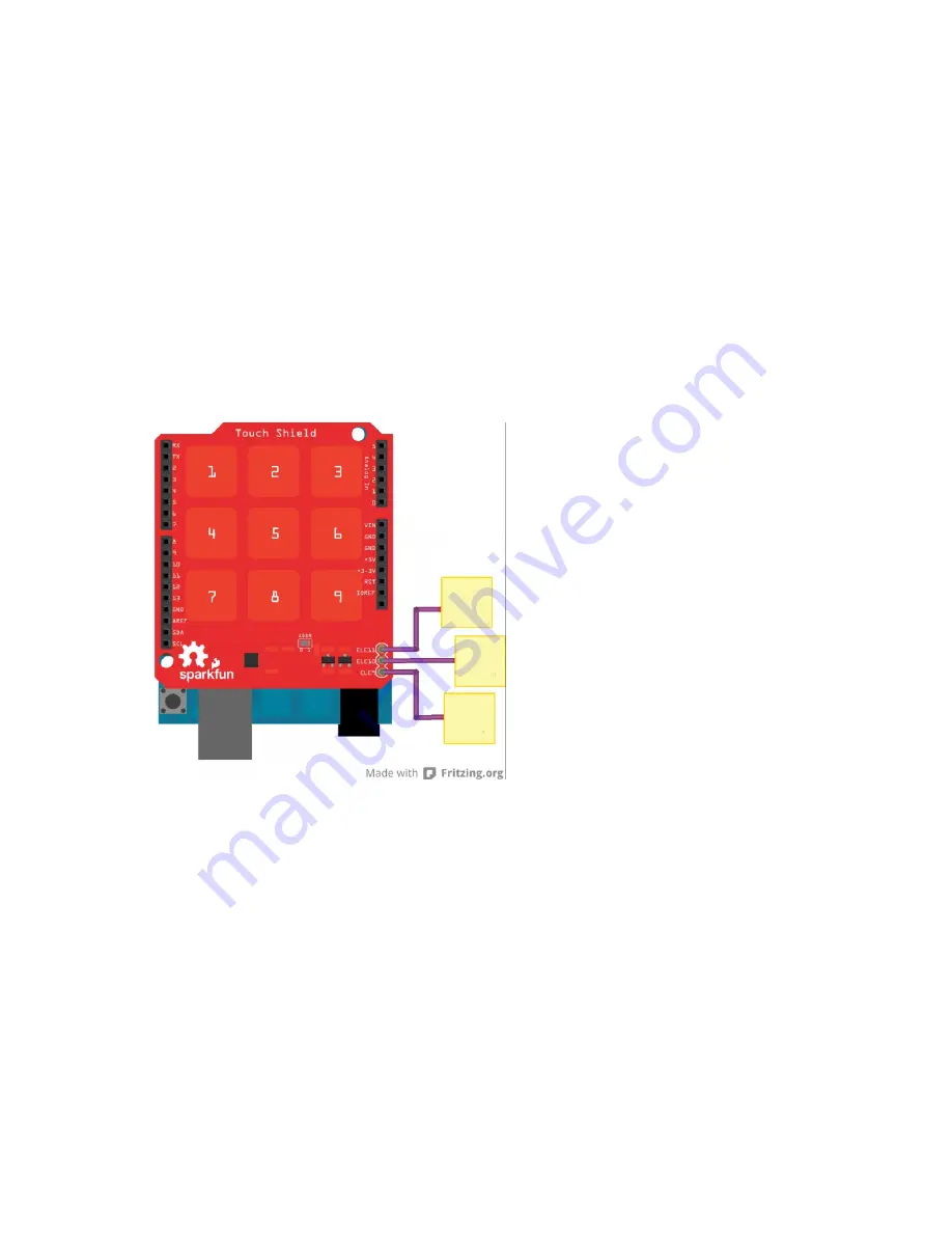
The shield also has 3 pins labeled ELE9, ELE10, and ELE11. These
correspond to electrodes 9,10, and 11 on the MPR121 chip. You can solder
additional buttons or connections on to these pins at this time if you want
more than the 9 buttons already available on the shield. However, you don’t
have to do this to get the shield to function. It’s up to you!
Check out the Fritzing diagram below to see how your shield should look if
you have added buttons on to your shield on pins ELE9, ELE10, and
ELE11.
Note:
The yellow squares represent whatever material you’ve chosen to
use as your electrode.
Once you’ve got your shield all hooked up, let’s start pulling data from the
shield!
Communicating with the Shield
Once you’ve got your shield assembled, it’s time to start talking to it! You
can download the example code here, or find the most up-to-date version in
the GitHub repository.
Open up the
Touch_Sensor_Shield_Example.ino
file. The other files set the
register definitions for the MPR121 chip, so you shouldn’t need to mess
with these at all.
Page 10 of 24


