background image

SY-P4RS350 / P4RC350 Quick Start Guide 

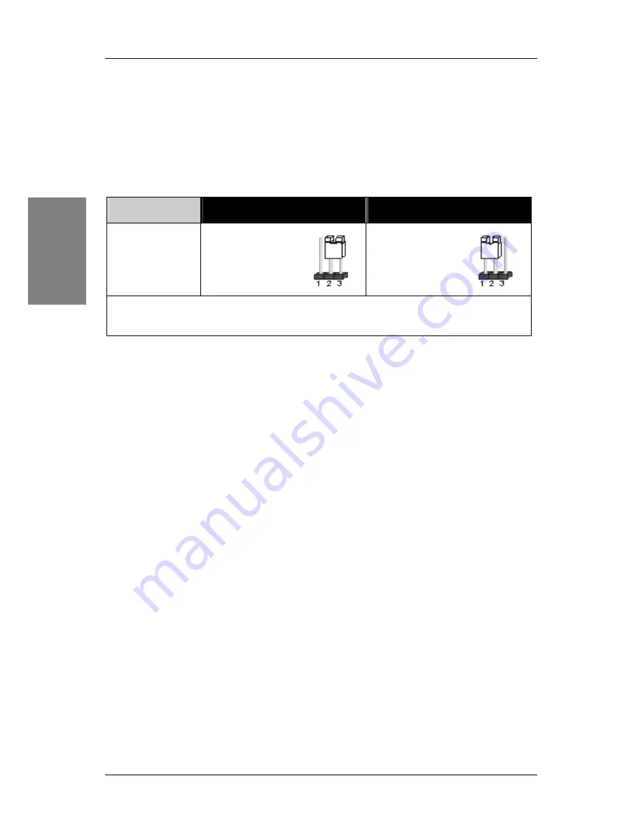
CMOS Clear (JP5)  

In some cases the CMOS memory may contain wrong data, follow the steps below to 
clear the CMOS memory. 

1. 

Clear the CMOS memory by momentarily shorting pin 2-3 on jumper JP5. Its 
white cap can easily identify this jumper.  

2. 

Put the jumper back to 1-2 to allow writing of new data into the CMOS memory. 

CMOS Clearing 

Clear CMOS Data 

Retain CMOS Data  

JP5 Setting 

Short pin 2-3 for  

at least 5 seconds 
to clear the CMOS  


Short pin 1-2 to 

retain new settings 


Note: You must unplug the ATX power cable from the ATX power connector 
when performing the CMOS Clear operation. 


Installa

tio


14

Содержание SY-P4RC350

Страница 1: ...Introduction USB 2 0 Driver Installation The SOYO CD Quick BIOS Setup Hardware Installation SY P4RS350 SY P4RC350 Motherboard Quick Start Guide ...

Страница 2: ...ormally preferably 350watts forminimalloadingor400 wattsfor fullyloadedsystem 4 If you have any problem getting your system to work please follow the troubleshootingtipsinyourusermanual 5 On some mainboards the actual chipset heatsink or fan may differ from the chipset cooler as shown on the picture or on the box However the chipset fanon the mainboard isof the same quality and will work just as w...

Страница 3: ...fringe upon any patents It is the policy of SOYO Computer Inc to respect the valid patent rights of third parties and not to infringe upon or to cause others to infringe upon such rights Disclaimer Please be advised that some SOYO motherboards are designed with overclocking features and may allow users to run the components beyond manufacturer s recommended specifications Overclocking beyond manuf...

Страница 4: ...p to 800 MHz Hyper Threading Technology designed to take advantage of the multitasking features in Windows XP gives you the power to do more things at once Unpacking When unpacking the motherboard check for the following items The SY P4RS350 P4RC350 AGP PCI Motherboard The User Quick Start Guide The Installation CD ROM One IDE Device ATA 100 Flat Cable One Floppy Disk Drive Flat Cable One Back Pan...

Страница 5: ...r PRT COM A RCA1 SVEDIO1 VGA Audio Chip LAN Chip Audio out Front out Audio in Rear out MIC IN Center Bass out P1 PCI Slot 1 PCI Slot 3 PCI Slot 2 1 1 2 2 CDIN1 DIMA1 DIMB1 DIMB2 DIMA2 IDE2 IDE1 FDC1 COM 2 JP5 AUXIN1 I O CHIP ATX1 SPDI1 SPDO1 USBLAN 16 2 J30 USB20_2 1 6 10 USB20_1 6 1 10 BAT1 HDD LED SUSP LED RST PWR 5 ...

Страница 6: ...nnector PRT COM A RCA1 SVEDIO1 VGA Audio Chip LAN Chip Audio out Front out Audio in Rear out MIC IN Center Bass out P1 PCI Slot 1 PCI Slot 3 PCI Slot 2 1 1 2 2 CDIN1 DIMB1 DIMB2 COM 2 JP5 AUXIN1 I O CHIP ATX1 SPDI1 SPDO1 USBLAN 16 2 J30 USB20_2 1 6 10 USB20_1 6 1 10 BAT1 HDD LED SUSP LED RST PWR IDE2 IDE1 FDC1 6 ...

Страница 7: ...es 184 pin 2 6V DDR DIMM sockets Supports PC2100 PC2700 and PC3200memory bus SY P4RS350 supports Dual channel DDR Four DIMM sockets up to 4GB memory capacity SY P4RC350 doesn t support Dual channel DDR Two DIMM sockets up to 2 GB memory capacity AGP 1x AGP master 4X 8X slot 1 5v only Integrated Graphics ATi Radeon 9100 Pro IGP 3D graphic engine PCI 3x 32 bit bus master PCI slots Rear Panel I O One...

Страница 8: ...allel ATA devices 2x IDE ports USB 2 0 6x USB 2 0 compliant ports 2x on rear 4x pin headers Sound Onboard C Media CMI9761A 6 channel Audio Codec Network 10 100 Mbps and 1000 Mbps Gigabit Ethernet controller BIOS Power Failure resume function to allow the system to turn on or off after a power failure which is indispensable for server systems Multiple boot allowing your system to boot from differen...

Страница 9: ...you through a quick and correct method to install your new motherboard For detailed information please refer to the motherboard User s Manual and Technical Reference online manual on the CD ROM package that came with your motherboard Gather and prepare all necessary components to complete the installation successfully Socket 478 processor with CPU cooling fan boxed type DDR RAM module s Computer c...

Страница 10: ... CPU Mount Procedure To mount the Pentium 4 Socket mPGA478 processor that you have purchased separately follow these instructions 1 1 3 4 2 1 Lift the socket handle up a vertical position 2 Align the blunt edge of the CPU with the matching pinhole edge on the socket 3 Processor in the socket without forcing 4 Then close the socket handle to secure the CPU in place Remember to connect the CPU Cooli...

Страница 11: ...and AGP cards claim part for your CPUs address space Installation Memory Configuration Table If you want to use the Dual Channel feature please follow the memory configuration table below DIMA1 DIMA2 DIMB1 DIMB2 128 bit Present Present 128 bit Present Present 128 bit Present Present Present Present DIMM Slots Performanc Dual Channel Performance Installing your memory in a combination different fro...

Страница 12: ...d 3 PCI slots 1 Read the instruction document of the related expansion card before inserting the expansion card into the computer 2 Press the expansion card firmly into expansion slot in the motherboard 3 Make sure the metal contacts on the card are correctly seated in the slot 4 Replace the screw to secure the slot bracket of the expansion card 5 Install driver for the operating system you use St...

Страница 13: ...N1 L G G R PWR LED Pin11 Pin12 Pin13 VCC NC GND SPKR Pin17 Pin18 Pin19 Pin20 VCC NC NC Speaker out HDD LED SUSP LED PWR RST SPKR RST PWR PWR LED HDD LED SUSP LED Pin9 Pin10 Pin7 Pin8 Pin4 Pin5 Pin1 Pin2 LEDAnode LED Cathode VCC GND Power GND Control PIN GND Power On Off PWRBT Connect your power switch to this header momentary switch type To turn off the system press this switch and hold down for l...

Страница 14: ...jumper JP5 Its white cap can easily identify this jumper 2 Put the jumper back to 1 2 to allow writing of new data into the CMOS memory CMOS Clearing Clear CMOS Data Retain CMOS Data JP5 Setting Short pin 2 3 for at least 5 seconds to clear the CMOS Short pin 1 2 to retain new settings Note You must unplug the ATX power cable from the ATX power connector when performing the CMOS Clear operation In...

Страница 15: ... UTILITY will be shown on the screen Then follow these steps to configure the CPU settings Step 1 Select STANDARD CMOS SETUP Set Date Time and Floppy drive type then set Hard Disk Type to Auto Step 2 Select LOAD OPTIMIZED DEFAULTS Select the LOAD OPTIMIZED DEFAULTS menu and type Y at the prompt to load the BIOS optimal setup Step 3 Select SAVE EXIT SETUP Press Enter to save the new configuration t...

Страница 16: ...ard in PDF format b The drivers software available for installation and c A database in HTML format with information on SOYO motherboards and other products d Panda Anti Virus software Step 1 Insert the SOYO CD into the CD ROM drive In that case the following dialog will pop up Please choose your motherboard model number and press OK Now the SOYO CD Start Up Menu will come up as shown on the follo...

Страница 17: ...you on whether or not you want to install it You must install the Acrobat Reader utility to be able to read the user s manual file Follow the instructions on your screen during installation Once the installation is completed restart your system and re run the SOYO CD Step 2 Install Drivers and Utilities Click the Install Drivers button to display the list of driver software that can be installed f...

Страница 18: ...YO CD This driver supports 2 4 6 speakers 3D positional audio for the onboard C Media audio chip VIA Gigabit Ethernet Driver for Win 98SE ME 2000 XP This program will install onboard LAN VIA LAN driver on your computer Wasay Pro Magic ProMagic is an instant system recovery software that provides convenient instant restoration to the preferred state at any specific restore time point as desired Was...

Страница 19: ...a restart of your system before they become active Step 3 Check the Latest Releases Click the Connect to SOYO website button to go the SOYO Website to find the latest BIOS manual and driver releases for your motherboard This button will only work if your computer is connected to the internet through a network or modem connection Make sure to get your internet connection up before clicking this but...

Страница 20: ...SY P4RS350 P4RC350 Quick Start Guide After Windows XP installation your device manager should look like this The SOYO CD 20 ...

Страница 21: ...SY P4RS350 P4RC350 Quick Start Guide After driver installation your Windows XP device manager should look like this The SOYO CD 21 ...

Страница 22: ...SY P4RS350 P4RC350 Quick Start Guide Drivers directory list in the CD driver Audiodriver LANdriver ATisoftwaredriver The SOYO CD 22 ...

Страница 23: ... asp Windows XP Service Pack1 Include USB2 0 Drivers After installing service pack1 please do the following 1 Go to the device manager 2 Remove 3 Restart your system Next time Windows XP starts up a new USB 2 0 controller will be found USB2 0 Driver Installation for Windows 2000 USB 2 0 drivers are available for download using Windows Update for Windows 2000 For additional information regarding US...

Страница 24: ...up no video no beeping sound heard but the CPU fan is turning 1 Clear CMOS RAM JP5 connector see Quick start guide for more info on how to clear the CMOS 2 Check all the jumper settings on the M B 3 Check if the CPU is ok by using another CPU check the Quick start guide for CPU supported on this M B 4 Check if the power supply is ok The minimum should be 350 watt for a minimally loaded system or 4...

Страница 25: ... and memory detects my hard drive floppy drive and CD ROM but locks up at Verify DMI pool data Don t go any further What should I do 1 Clear CMOS battery JP5 connector see Quick start guide for more info on how to clear the CMOS 2 If still has the problem remove all other add on cards except the video cards see if it boots further Then put peripherals in one by one to identify which one causes the...

Страница 26: ...o card Hard disk See if you can finish Windows installation Then put peripherals in one by one to identify which one causes the lockup BIOS Issue Where can I find the BIOS revision of my mainboard It will be displayed on the up left corner on the screen during boot up It will show as your board type followed by the revision number such as kvxa_2BA1 meaning BIOS revision 2BA1 for the SY K7V Dragon ...

Страница 27: ... other way you need to send back the BIOS ROM to your nearest SOYO branch for re flashing VGA Issue I cannot set my VGA to go higher than 16 color 640x 480 1 Make sure that you have installed the ATI utility driver set 2 Install re install the VGA driver Audio Issue I cannot get the sound working on my system 1 Check if the speaker wire is connected to the line out connector in the M B 2 Check if ...

Страница 28: ...re and the LED on the floppy stays on 1 Make sure the red wire of floppy ribbon cable goes to Pin1 on the floppy drive side don t trust the key lock or notch and use the end connector of the cable don t use middle one 2 Some floppy drivers have their own jumper to make the same twist as the twist on the cable Make sure this jumper is set not to twist the cable while the floppy drive is connected t...

Страница 29: ... you live in TAIWAN SOYOEnterpriseLtd 1stF No 38 Lane15 Sec 6 MinquanEast Road NeihuDistrict TaipeiCity11494 Taiwan R O C Tel 886 2 2791 5688 Fax 886 2 2791 8599 http www soyo com Email info mail soyo com tw USA SOYO INC 1420 S Vintage Ave Ontario CA 91761 USA TEL 909 292 2500 FAX 909 937 0783 http www soyousa com http www soyousa com kb For technical support GM SOYO Deutschland GmbH Gewerbepark 8...

Отзывы: