background image

Table of Contents

SY-6IEB

iii

Table of Contents

SY-6IEB MAINBOARD LAYOUT...................................................1

CHAPTER 1 INTRODUCTION .....................................................2

1-1

KEY FEATURES......................................................2

1-2

HANDLING THE MAINBOARD ................................5

1-3

ELECTROSTATIC DISCHARGE PRECAUTIONS ....5

CHAPTER 2 HARDWARE SETUP ...............................................6

2-1

PREPARATIONS .....................................................6

2-2

UNPACKING THE MAINBOARD..............................7

2-3

INSTALLATION GUIDE............................................8

CHAPTER 3 BIOS SETUP UTILITY ...........................................31

3-1

SOYO COMBO SETUP .........................................33

3-2

STANDARD CMOS SETUP ...................................37

3-3

BIOS FEATURES SETUP ......................................40

3-4

CHIPSET FEATURES SETUP ...............................45

3-5

POWER MANAGEMENT SETUP...........................49

3-6

PNP/PCI CONFIGURATION SETUP......................53

3-7

LOAD SETUP DEFAULTS .....................................56

3-8

INTEGRATED PERIPHERALS...............................57

3-9

SUPERVISOR PASSWORD ..................................61

3-10

USER PASSWORD ...............................................62

3-11

IDE HDD AUTO DETECTION ................................63

CHAPTER 4 DRIVERS INSTALLATION.....................................64

Содержание SY-6IEB

Страница 1: ...SY 6IEB Mainboard User s Guide Technical Reference...

Страница 2: ...he product described within it at any time without notice and without obligation to notify any person of such revision or change The information contained in this manual is provided for general use by...

Страница 3: ...6 2 2 UNPACKING THE MAINBOARD 7 2 3 INSTALLATION GUIDE 8 CHAPTER 3 BIOS SETUP UTILITY 31 3 1 SOYO COMBO SETUP 33 3 2 STANDARD CMOS SETUP 37 3 3 BIOS FEATURES SETUP 40 3 4 CHIPSET FEATURES SETUP 45 3...

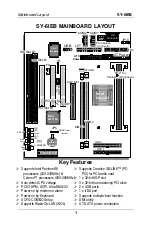
Страница 4: ...astering PCI slots 2 x USB ports 1 x IrDA port Supports multiple boot function DMI utility AT ATX power connectors IDE 1 1 IDE 2 1 ISA Slot 2 1 3V Lithium Battery PCI Slot 3 JP44 1 3 Intel 82371 EB In...

Страница 5: ...standards and adds many technical enhancements 1 1 KEY FEATURES Supports Intel Pentium II processors 233 333MHz Supports Celeron processors 266 366MHz Auto detect CPU voltage PC97 ACPI Ultra DMA 33 S...

Страница 6: ...xed type CPUs Features Auto detection of CPU voltage Chipset 82440 EX LX AGP PCI Set ATX Power 20 pin Male Connector CPUFAN 3 pin CPU Cooling Fan Connector CHAFAN 3 pin Chassis Cooling Fan Connector M...

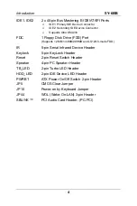
Страница 7: ...s 1 2MB 1 44MB 2 88MB and LS120 3 mode FDD IR 5 pin Serial Infrared Device Header Keylock 5 pin KeyLock Header Reset 2 pin Reset Switch Header Speaker 4 pin PC Speaker Header TB_LED 2 pin Turbo LED He...

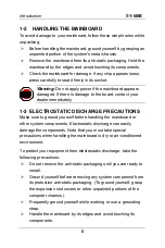
Страница 8: ...1 3 ELECTROSTATIC DISCHARGE PRECAUTIONS Make sure to ground yourself before handling the mainboard or other system components Electrostatic discharge can easily damage the components Note that you mus...

Страница 9: ...e installation successfully 1 Pentium II or Celeron processor with built in CPU cooling fan boxed type Note This mainboard supports non boxed type CPUs The heavier CPU cooling fan requires the install...

Страница 10: ...with 9 pin flat cable If your board comes with a driver disc and a paper manual the Quick Start Guide and the CD ROM are not included in the package Warning Do not unpack the mainboard from its anti...

Страница 11: ...devices before performing any work on the mainboard or system BEGIN THE INSTALLATION Step 1 CPU Installation Your SY 6IEB mainboard comes with a CPU retention set kit The retention set is used to hold...

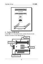
Страница 12: ...orting Base Support Clip Screws x2 Retention Clip Latches x2 2 Position the Mainboard Locate Slot 1 on the mainboard and position the board in the direction as shown in the following figure ATX Power...

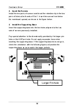
Страница 13: ...e Supporting Base Insert the supporting base into the two holes adjacent to the two sets of screws previously installed Pay special attention to the directionality provided by the larger pin hole on t...

Страница 14: ...B 11 5 Install the Retention Clip Set the retention clip centered on Slot 1 and right on top of the two sets of screws along side Slot 1 as shown in the following figure Then tighten the four screws o...

Страница 15: ...are Setup SY 6IEB 12 6 Install the CPU Insert the CPU into the retention clip and lock the two latches on the sides of the CPU to secure the Pentium II processor in place as shown in the following fig...

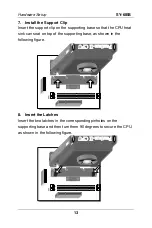
Страница 16: ...orting base so that the CPU heat sink can seat on top of the supporting base as shown in the following figure 8 Insert the Latches Insert the two latches in the corresponding pinholes on the supportin...

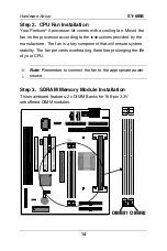
Страница 17: ...provided by the manufacturer The fan is a key component that will ensure system stability The fan prevents overheating therefore prolonging the life of your CPU Note Remember to connect the fan to the...

Страница 18: ...nstallation HDD CD ROM This mainboard offers two primary and secondary IDE device connectors IDE1 IDE2 It can support up to four high speed HDD or CD ROM Connect one side of the 40 pin flat cable to t...

Страница 19: ...enabling or disabling the keyboard Connect the KeyLock switch to the 5 pin Keylock header on the mainboard Please install according to the following pin assignment pin 1 3 are for Power LED and pin 4...

Страница 20: ...ystem is in Turbo mode The manufacturer has permanently set this mainboard in Turbo mode due to most hardware and software compliance to turbo mode 5 IDE LED Attach the 2 pin IDE device LED cable to t...

Страница 21: ...s COM1 COM2 first install the external connectors that come with your Mainboard on the computer case then plug the other end of the flat cable to their respective connectors Only after you have fixed...

Страница 22: ...eir respective 10 pin flat cable connectors into the COM1 and COM 2 serial port connectors on the mainboard The bracket should be fixed to one of the slots at the back of the computer case using a scr...

Страница 23: ...as shown in the figure below then fix the bracket to one of the slots at the back of the computer case using a screw After having finished this you can plug any parallel device into the back panel con...

Страница 24: ...iversal Serial Bus USB This mainboard provides a dual row 10 pin header one pin is empty to support two USB ports for your additional devices Attach the USB cable Optional to this header as shown in t...

Страница 25: ...computer through the LAN card Please install according to the following pin assignment 2 Infrared IR Plug the 5 pin infrared device cable to the IR header This will enable the infrared transfer funct...

Страница 26: ...up Utility POWER MANAGEMENT menu To avoid damage to the system install according to the following pin assignment 2 Chassis Cooling Fan Some chassis also feature a cooling fan This mainboard features a...

Страница 27: ...PCI or ISA expansion slots according to card specifications Step 11 PCI Audio Card Some PCI soundcards require a PC PCI DMA channel Attach the 5 pin cable from your creative sound blaster PCI audio c...

Страница 28: ...B to meet the standard ATX specification Note If you use the Wake On LAN WOL or Power on by keyboard function make sure the ATX power supply can support at least 720 mAmp on the 5V Standby lead 5VSB P...

Страница 29: ...Setting Short pin 1 2 to retain the new CMOS settings Short pin 2 3 for at least 5 seconds to clear the CMOS Note You must unplug the ATX power cable from the ATX power connector when performing the C...

Страница 30: ...l you get the following screen 3 The BIOS Setup screen appears Step 17 Quick BIOS Setup This mainboard does not use any hardware jumpers to set the CPU frequency Instead CPU settings are software conf...

Страница 31: ...MOS SETUP Set Date Time and Floppy drive type then set Hard Disk Type to Auto 3 Select SOYO COMBO SETUP Move the cursor to the CPU Speed field to set the CPU working frequency as shown in the followin...

Страница 32: ...es Note Mark the checkbox that corresponds to the working frequency of your Pentium II processor in case the CMOS configuration should be lost 4 Select SAVE EXIT SETUP Press Enter to save the new conf...

Страница 33: ...nu of Windows 95 98 to turn off your computer 2 Press the mechanical power button and hold down for over 4 seconds to shutdown the computer If you press the power button for less than 4 seconds then y...

Страница 34: ...the Main Menu press arrow keys to enter the selected submenu Modifying selected items l Use the Up Down keys to modify values within the selected fields Some fields let you enter values directly ROM P...

Страница 35: ...M O S S E T U P U T I L I T Y A W A R D S O F T W A R E I N C S T A N D A R D C M O S S E T U P B I O S F E A T U R E S S E T U P C H I P S E T F E A T U R E S S E T U P P O W E R M A N A G E M E N T...

Страница 36: ...BO SETUP option from the main menu and press the Enter key The SOYO COMBO SETUP menu combines the main parameters that you need to configure all in one menu for a quick setup in BIOS ROM PCI ISA BIOS...

Страница 37: ...CPU Frequency If CPU Speed field is set to Manual CPU Ratio After you have selected the host clock choose the right multiplier for the CPU Options are 2 2 5 3 3 5 4 4 5 5 5 5 The CPU frequency is then...

Страница 38: ...DROM C A D A SCSI E A SCSI F A SCSI SCSI A C SCSI C A C only Boot Sequence LS ZIP C Choose the boot sequence adapted to your needs for example l A C SCSI means the BIOS will look for an operating syst...

Страница 39: ...Set the password that will wake up your system If POWER ON Function is set to Hot Key KBPowerON Password Ctrl F1 F12 Choose the key combination that will wake up the system Ctrl F1 to Ctrl F12 Instant...

Страница 40: ...time 24 hour clock format 3 15 PM is displayed as 15 15 00 ROM PCI ISA BIOS STANDARD CMOS SETUP AWARD SOFTWARE INC Date mm dd yy Time hh mm ss Wed August 26 1998 11 30 33 HARD DISKS TYPE SIZE CYLS HEA...

Страница 41: ...E hard disk 528MB LBA Enhanced IDE hard disk 528MB Mode Large Large IDE hard disk for certain hard disk Note If you have any questions on your hard disk type or mode ask your hard disk provider or pre...

Страница 42: ...EGA VGA Default CGA 40 CGA 80 Mono Monochrome 3 2 5 Halt On When the BIOS detects system errors this function will stop the system Select which type of error will cause the system halt All Errors Defa...

Страница 43: ...00 DBFFF Shadow DC000 DFFFF Shadow Enabled Disabled Disabled Disabled Disabled Disabled Disabled ESC F1 F5 Quit Help Old Values PU PD Shift F2 Select Item Modify Color Virus Warning CPU Internal Cache...

Страница 44: ...ote Disabled CPU Internal Cache Enabled Enables the CPU s internal cache Default Disabled External Cache Enabled Enables the external memory Default 3 3 3 System Boot Control Settings System Boot Cont...

Страница 45: ...ar sec 30 Char sec Choose the rate at which a character is repeated when holding down a key Default Typematic Delay 250 msec 500 msec 750 msec 1000 msec Choose how long after you press a key down the...

Страница 46: ...ing Default OS2 When using an OS2 operating system OS Select for DRAM 64MB Non OS2 When using another non OS2 operating system Default Disabled Default HDD S M A R T capability Enabled Enable this fie...

Страница 47: ...K segment if it is enabled and if it has BIOS present These 16 segments can be shadowed from ROM to RAM BIOS shadow copies BIOS code from slower ROM to faster RAM BIOS can then execute from RAM Defaul...

Страница 48: ...I ISA BIOS CHIPSET FEATURES SETUP AWARD SOFTWARE INC Spread Spectrum Disabled ESC F1 F5 Quit Help Old Values PU PD Shift F2 Select Item Modify Color Auto Configuration DRAM Speed Selection MA Wait Sta...

Страница 49: ...nabled DRAM Speed Selection 60ns 50ns Choose the DRAM speed that will produce the appropriate DRAM timing for your system Default The following MA Wait State EDO RAS To CAS Dealy EDO RAS Precharge Tim...

Страница 50: ...ble Enabled The ROM area A0000 BFFFF is cacheable 8 BIT I O Recovery Time 1 NA 2 8 Use the default setting Default 16 BIT I O Recovery Time 1 NA 2 4 Use the default setting Default Disabled Default Me...

Страница 51: ...e the default setting Default SDRAM RAS Precharge Time Fast Slow Use the default setting Default SDRAM Cache Latency Time 3 2 Use the default setting Default SDRAM Precharge Control Disabled Enabled U...

Страница 52: ...0 Primary IDE 1 Secondary IDE 0 Secondary IDE 1 Floppy Disk Serial Port Parallel Port Enabled Disabled Disabled Disabled Disabled Disabled Enabled Disabled ESC F1 F5 Quit Help Old Values PU PD Shift...

Страница 53: ...end timer HDD power down Min Saving 1 Hour 1 Hour 1 Hour 15 Min Power Management Max Saving 1 Min 1 Min 1 Min 1 Min Yes To use Advanced Power Management APM you must run power exe under DOS V6 0 or la...

Страница 54: ...to User Define Disable Default Standby Mode 1Min 1Hour When the set time has elapsed BIOS sends a command to the system to enter Standby Mode The following Suspend Mode field may be configured only i...

Страница 55: ...er Down Resume Events Setting Description Note Disabled IRQ 3 7 9 15 NMI Enabled The system monitors these elements for activity The system will resume if an IRQ activity is detected Default Disabled...

Страница 56: ...p To Primary IDE INT Secondary IDE INT Used MEM base addr Assign IRQ For USB PCI AUTO A B N A Disabled ESC F1 F5 Quit Help Old Values PU PD Shift F2 Select Item Modify Color IRQ 3 IRQ 4 IRQ 5 IRQ 7 IR...

Страница 57: ...If there is any doubt set this field to No Manual BIOS does not manage PCI ISA PnP card IRQ assignment Requires to assign IRQ and DMA to PCI or ISA PnP manually IRQ 3 4 5 7 9 10 11 12 14 15 assigned t...

Страница 58: ...2 14 15 DMA 0 1 3 5 6 7 N A Default Used MEM base addr I O address C800 CC00 D000 D 400 D800 DC00 Asking card provider for the exactly I O address of this add on card Use this function only when probl...

Страница 59: ...s Warning If you run into any problem after changing the BIOS configuration please load the SETUP DEFAULTS for stable performance ROM PCI ISA BIOS CMOS SETUP UTILITY AWARD SOFTWARE INC SOYO COMBO SETU...

Страница 60: ...ports ROM PCI ISA BIOS INTEGRATED PERIPHERALS AWARD SOFTWARE INC Onboard Parallel Port Parallel Port Mode ECP Mode Use DMA 378 IRQ7 SPP 3 ESC F1 F5 Quit Help Old Values PU PD Shift F2 Select Item Modi...

Страница 61: ...er performance and stability we suggest you use the Auto setting to set the HDD control timing Default Disabled IDE Primary Master UDMA Primary Slave UDMA Auto Select Auto to enable Ultra DMA Mode sup...

Страница 62: ...8 IRQ4 2E8 IRQ3 Onboard UART 1 Onboard UART 2 Auto Choose serial port 1 2 s I O address Do not set port 1 2 to the same address except for Disabled or Auto Standard Supports a Standard serial infrared...

Страница 63: ...device that connects to this port If Parallel Port Mode is set to ECP mode 3 Choose DMA3 Default ECP Mode use DMA 1 Choose DMA1 3 8 6 MULTI I O ADDRESSES Default settings for multi I O addresses are a...

Страница 64: ...word is required every time the system is booted This means only a person who knows the password can use this computer b Setup The password is required only when you attempt to enter the BIOS Setup pr...

Страница 65: ...on 3 9 ROM PCI ISA BIOS CMOS SETUP UTILITY AWARD SOFTWARE INC STANDARD CMOS SETUP BIOS FEATURES SETUP CHIPSET FEATURES SETUP POWER MANAGEMENT SETUP PNP PCI CONFIGURATION LOAD SETUP DEFAULTS LOAD BIOS...

Страница 66: ...cordingly Note This function is only valid for IDE type of hard disk drives ROM PCI ISA BIOS CMOS SETUP UTILITY AWARD SOFTWARE INC HARD DISKS TYPE SIZE CYLS HEAD PRECOMP LANDZ SECTOR MODE Primary Mast...

Страница 67: ...the drivers software available for installation and a database in HTML format with information on SOYO mainboards and other products The SOYO CD Start Up Program automatically detects which SOYO main...

Страница 68: ...Drivers Installation SY 6IEB 65 Step 2 Install Drivers The following drivers are available for Windows 95 The following drivers are available for Windows 98...

Страница 69: ...mainboards click the Display all drivers on the SOYO CD button Please make sure to install only the drivers adapted to your system or otherwise this cause system malfunctions Step 3 Select which drive...

Страница 70: ...67...
Отзывы: