


Introduction
3
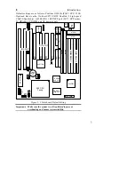
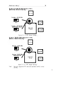
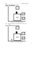
Mainboard Layout w/ Default Settings
7
8
4
2
2
3
3
1
5
6
19
14
11
13
12
9
10
15
16
17
18
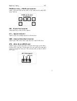
Figure 1Ð1. Mainboard Layout
1. ZIF socket 7 (for P54C/P55C)
11. Floppy Connector
2. 82430 TX Chipset
12. IDE1/IDE2 Connector
3. Pipelined Burst SRAM
13. Parallel Port Connector
4. Ultra I/O Chip
14. COM1/COM2 Connector
5. PnP FLASH BIOS
15. AT Power Supply
Connector
6. TAG SRAM
16. AT/ATX Power Connector
7. ISA Slots
17. PS/2 Mouse Connector
8. PCI Slots
18. KB Connector
9.
10.
SIMM Bank
Unbuffered DIMM Bank
19. Lithium battery (for
CMOS memory, 3V)


