background image

12

Electrical Connection

www spe pv com

.

-

.

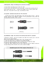
6.4Installation Steps of Ordinary DC connector Terminal

.
.


.


.


.


 ,


  .

a Strip off the insulating layer of wire for 7mm
b Twist off the red and black cap of terminals

Connect the positive pole of

solar system with red one

Connect the negative pole of solar system with

black one

Then twist on the caps

and fixed the cable

(1)  Specific terminal connection for PV connector

(2) Installation steps for connect the terminal with the PV connector

            ,

     .


.

.


,


.

.

.


.

.


.

.


.

.


.

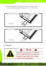
Connect the inverter and photovoltaic array with the MC4 connect

link the

positive terminal and negative terminal of the photovoltaic array with the
corresponding terminals of the inverter

A Ready for cables

strip the insulation and bare the copper line in the tail

cable for 7mm approximately
B Put metal terminal in the middle hole of the Crimping pliers.
C Insert the cable which is stripped in the metal terminal
D Press the metal terminal with the Crimping pliers to fixed the cable
E Pass the cable through the nuts of the connector
F Insert the metal terminal into the male connector and the female connector
correspondingly and screw the nuts of the connects tightly

6-4-

2

DC+

DC-

Installation picture or V onnector

icture6


(  

- - )

f

P C

P

4 3

Содержание 100W Grid

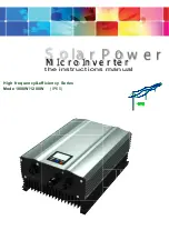
Страница 1: ...Grid High frequency efficiency Series Mode 1000W 1200W IP65 http www new pv com http www new pv com o la r P o w e r S the instructions manual M I c r o In v e r te r...

Страница 2: ...pilot lamp 5 3 6 Operation mode for grid connected inver 7 4 fault treatment 5 Installation 5 1 Installation Sites 8 5 2 Installation for Inverter 9 6 Electrical connections and commissioning 6 1 Req...

Страница 3: ...t will be showed on the LCD LED This Inverter Having multiple design patent it has technical Features of high integration density about electrical design s i m p l e a n d e a s y c o n s t r u c t e...

Страница 4: ...nsportation company or company to contact with me directly Please provide photos of the damage we will provide the fastest the best service Before install and operate should read the enchiridion caref...

Страница 5: ...ranslated into DC current by solar panel array and it is translated into the common frequency and in phase with power grid by grid tied inverter then Feed into the grid it is thus clear that the grid...

Страница 6: ...t ready to grid tied Blue MPPT Track Input Voltage Is beyond the scope of MPPT tracking Trying to Track the MPPT maximum power point of solar panels Locked the MPP RED Temperature Stoppage Temperature...

Страница 7: ...Such as Max Working Voltage Range of AC Voltage DC Input Voltage Range MPPT Voltage Range etc 1 The Inverter has Self inspection mode for 10 seconds it will check AC Voltage frequency DC Voltage It w...

Страница 8: ...dule is below a certain value or the grid parameters such as voltage frequency temperature is beyond the scope of work permit grid inverter in the standby state ormal shutdown When the light intensity...

Страница 9: ...neration efficiency Installation Before installation please read the installation instructions carefully First should ensure the installation location is stable and safe The size of the micro inverter...

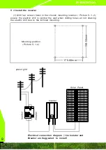
Страница 10: ...ocation Picture 5 1 2 ensure the electric drill is vertical the wall when drilling holes an not shaking the electric drill due to the inclined mounting Mounting position Picture 5 1 2 175 00mm power g...

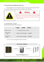
Страница 11: ...nection step 6 1 Specification of Cable Please note this before the installation 1200W Solar Array DC 1000W 1500W Please connect the inverter without AC and DC Voltage The open circuit voltage of the...

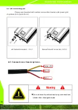
Страница 12: ...ect the Inverter with power grid As picture 6 3 1 and 6 3 2 AC Cable Connection 6 3 1 6 3 2 Done with the AC connection Electrical Connection Do not insert and extract any connectors Under the charged...

Страница 13: ...rray with the MC4 connect link the positive terminal and negative terminal of the photovoltaic array with the corresponding terminals of the inverter A Ready for cables strip the insulation and bare t...

Страница 14: ...owing pictures Picture6 4 4 Picture 6 4 5 6 4 5 Check the solar panels at no load open circuit voltage of the machine within the allowable range If there is overvoltage the device may be damaged Warni...

Страница 15: ...the previous steps the gird voltage and DC side voltage is normal the micro inverter will automatically start parallel operation DC input parameters Recommended solar panel board power uses W DC in br...

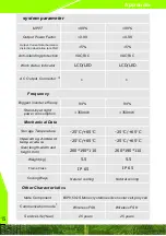
Страница 16: ...wer Factor Output Current total harmonic distortion aberration tate THD Anti islanding ptotection system parameter 25 years Frame Class Other Characteristics Mate Component Communication mode Service...

Страница 17: ...the contract shall prevail 2 Need warranty occurs in the warranty period the company may require customers to show to buy paper and the corresponding serial ID code of the warranty card and certifica...

Страница 18: ...ree of charge and copyright statement 1 If there are some changes about the product size and parameter Will be subject to the company information without prior notice 2 Electrical products should cons...

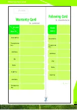
Страница 19: ...name Telephone No Address Zip Name Model Date Agency Warranty Card Following Card to manufacturer to customer Model Name Username Telephone No Address Zip Date Seal Address Agency Telephone No Warrant...

Отзывы: