


17
SERVICE AND ADJUSTMENTS
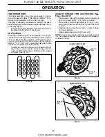
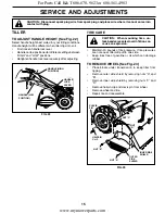
BELT GUARD
SCREW
HAIRPIN CLIP AND
CLEVIS PIN
HEX NUT
AND WASHER
(LOCATED
BEHIND
TIRE)
FIG. 27
FIG. 28
SCREW
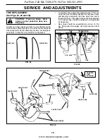
TO REMOVE BELT GUARD (See Fig. 27)
•
Remove hairpin clip and clevis pin from left wheel.
Pull wheel out from tiller about 1 inch.
• Remove cap nut and washer, and hex bolt and washer
from side of belt guard.
• Remove hex nut and washer from bottom of belt guard
(located behind wheel).
• Pull belt guard out and away from tiller.
• Replace belt guard by reversing above procedure.
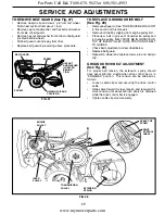
TO REPLACE GROUND DRIVE BELT
(See Fig. 28)
• Remove belt guard. (See “TO REMOVE BELT GUARD”
in this section of this manual).
• Remove old belt by slipping from engine pulley fi rst.
• Place new belt in groove of transmission pulley and
into engine pulley. BELT MUST BE IN GROOVE ON
TOP OF IDLER PULLEY. NOTE POSITION OF BELT
TO GUIDES.
• Check belt adjustment as described below.
• Replace belt guard.
• Reposition wheel and replace clevis pin and hairpin
clip.
GROUND DRIVE BELT ADJUSTMENT
(See Fig. 28)
For proper belt tension, the extension spring should
have about 5/8 inch stretch when drive control bar is in
“EN GAGED” position. This tension can be attained as
follows:
• Loosen cable clip screw securing the drive control
cable.
• Slide cable forward for less tension and rearward for
more tension until about 5/8 inch stretch is obtained
while the drive control bar is engaged.
• Tighten cable clip screw securely.
CABLE CLIP
SCREW
DRIVE
CONTROL
CABLE
EXTENSION
SPRING
ENGINE
PULLEY
IDLER
PULLEY
TRANS MIS SION
PULLEY
For Parts Call K&T 606-678-9623 or 606-561-4983
www.mymowerparts.com


