


P
LATINUM
S
ERIES
R
ANGE
PAGE
46
OF 47
OWNER’S MANUAL 1185836 REV 8 (9/14)
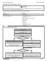
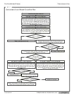
Figure 17
Convection-Oven Blower Does Not Run
DISCONNECT POWER AT CIRCUIT BREAKER.
Convection-oven blower does not run.
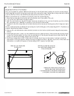
Open the kick panel below the oven door by raising it slightly and
tilting the top edge outward. Locate the door switch and check that
one wire is connected to the common (90° bottom) terminal of the
switch. Move the other wire to the normally open (lower leg)
terminal on the side of the door switch.
Check power supply to range.
Does the measured
voltage match the rated voltage
of the range?
Is there continuity?
No
Yes
DISCONNECT POWER AT CIRCUIT BREAKER.
Remove the control knobs from the front of the range. Remove the
screws that secure the top of the control panel and carefully tilt the
panel forward to expose the back of the blower switch that is
mounted in the front panel.
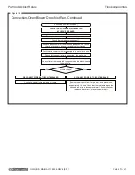
CAUTION: Be careful not to damage
the wiring behind the control panel.
Remove the protective cover
from the blower control switch.
Replace the blower control switch.
Check that the switch wires and terminals are secure.
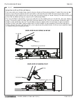
Reconnect the power supply. Use a voltmeter to measure the
voltage across the center terminals of switch wires 1 and 2.
Use a multimeter to check the continuity across the terminals of
blower-switch wires 1 and 3 (refer to the appropriate wiring diagram
in this manual or on the range). With the switch in the ON position,
there should be continuity.
Yes
No
Re-assemble the switch cover and control panel. Turn on the
blower-control switch and open the oven door.
Does the blower
run with the oven door
open?
No
Yes
Open the kick panel below the oven door by raising it slightly and
tilting the top edge outward. Locate the door switch and check for
continuity across the wired switch terminals while pressing the
switch actuator lever.
DISCONNECT POWER AT CIRCUIT BREAKER.
Loosen the two screws on the door switch bracket and adjust it so
that the door switch is pressed when the oven door is closed.
Replace door switch.
Close the oven door (which should
press the door-switch actuator lever).
Is there continuity?
No
Yes
Is there continuity?
No
Yes
Continue on next page.
T
ROUBLESHOOTING


