from
audio signal wires. [NOTE: Wires
audio signals
cross power wire, but
alongside it.)
You con route the
wires under the carpeting, but make
hey do
not interfere with the vehicle’s
Keep all wires inside
the vehicle, hidden from
An exposed wire can
be pulled out, and
or shorting
location and Mounting
The
is compact in size and it
virtually no
It con be
located almost
within the
trunk, or
storage
However,
not
the SVX4 in the engine comport-
ment, or in any outside location exposed to dirt and moisture.
Use the
a
to
holes. Before
to your vehicle’s c
the site for
hidden
or
you ore
the
of new system, we suggest “bench
testing” your entire system prior mounting ony components. By con-
necting the system to on
2 V dc
source,
con
the components outside the vehicle to verify your instollotion scheme.
Otherwise
system
connecting the system components to your vehicle’s
mounting
component.
In either
connect
intended in the final
power connections lost, test the system, and then
disconnect all
until final
is complete.
Connecting
Audio Signal
and Power Wires
sure power to your audio system is off.
2. Connect audio signal cables according to your
NOTE: For high level inputs, insert the bare-end wires from the
radio harness into he openings located on the enclosed mole barrier
strip connector. Follow the wire codes screened on the
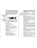
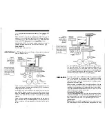
shown in Figure After tightening the screws at
open-
ing, insert the connector into the matching female connector on the
3. Connect the block
to good chassis ground (e.g., bare metal or
bolt, not pointed or
4. Connect the orange wire to your head unit’s
turn-on
This enables the
timed sequence for minimal
and turn-off thumps.
5. If desired, connect the orange/black wire (from the High Current
Remote Output de
circuit) to the power
remote input
connection (for omp
turn-on
6. Connect the red wire directly, through 0.5 A in-line (fast-blow)
(use, to constant
2 Vdc
so
it is “hot,”
the
ignition is off. Try connecting it to
battery cable itself, or
into a power
on an amplifier.
SETTINGS
AND
ADJUSTMENTS
1
level
to their minimum positions (i.e.,
counter-cl&vise). Set all
to their
12
positions. Turn the system on
verify
Power
indicator is on.
NOTE: If you ore using the high input connections, set the level match
control
ot the mid-point position. After completing step 4,
level
if
need
or cut the
initial
2. Set the hwd unit
to ik mid-
CD or tape, and
up
SVX4
int position, ploy your
t output level controls
(i.e., Sot/Mid ond Tweeter in
until the music reaches
listening level.
3. Next,
the SVX4
control until it is almost at the some
level
the front
This setting will
more
4.
the
control for
amount of bass,
ing to your
in music.
settings depend on
the
tics your
and the acoustics of your vehicle.
mak-
ing ony adjustments, check the loudspeaker owner’s
for ony
specific crossover recommendations.
follow these steps to
adjust the
crossover controls:
5. Adjust the
mid frequency controls (or satellite frequency
in
listening to
side of the initial 12
position on
the
to either
note ony differences in the
With
you’ll
the setting
sounds
best.
6. Adjust the
frequency in
described in step 5.
This time listen to the bars. You should find setting that will give
you solid sound with minimum “boom” from resonating frequen-
cies. Experiment with the 12
button. The 24
slope will
produce “tight”
bass, while the 12
slope will
stereo bass.


