5
10. PAGING MIC INPUT / RECORDING MIC INPUT
An input jack to connect a Paging MIC. It is recommended to use a balanced MIC.
11. PAGING MIC LEVEL CONTROL / RECORDING MIC LEVEL CONTROL
This potentiometer allow to adjust broadcasting and recording built-in DRP IC output level.
12. TALK BUTTON
You can start broadcasting by selecting the desired area and pressing and holding the TALK
button when performing Paging MIC broadcasting. In this case, character “P” is displayed
on the BGM input channel display window equivalent to the selected area. you can terminate
broadcasting by releasing, and the selected zone is released.
13. PAGING ZONE SELECTION BUTTON
Press the Button to select the zone that you want to broadcasting
.
14. REC BUTTON
By pressing and holding this button for a time allows you to enter RECORD READY mode
and you can see “-RECORD- “on the 7-segment displays.
Another long press of this button again, you can start recording and can see the rotating “-” mark
on the edge display.
Pressing this button a third time will end the recording.
15. BGM INPUT LED AND BGM SOURCE LABEL
A LED of the input channel, where BGM signal comes from, turns on.
16. MASTER/SLAVE LED
Displays mode in link of PM-88. This turns on depending on the status of the rear System
Mode switch.
17. POWER SWITCH
A switch to apply power supply to the system.
Front Panel
Содержание EM32
Страница 2: ......
Страница 16: ...Connections 14 Connections EM32 WP 8A ER 1 Sound input CA8240 Power Amplifier WP 8A EM ...
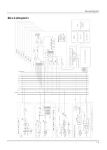
Страница 17: ...Block diagram 15 Block diagram ...


