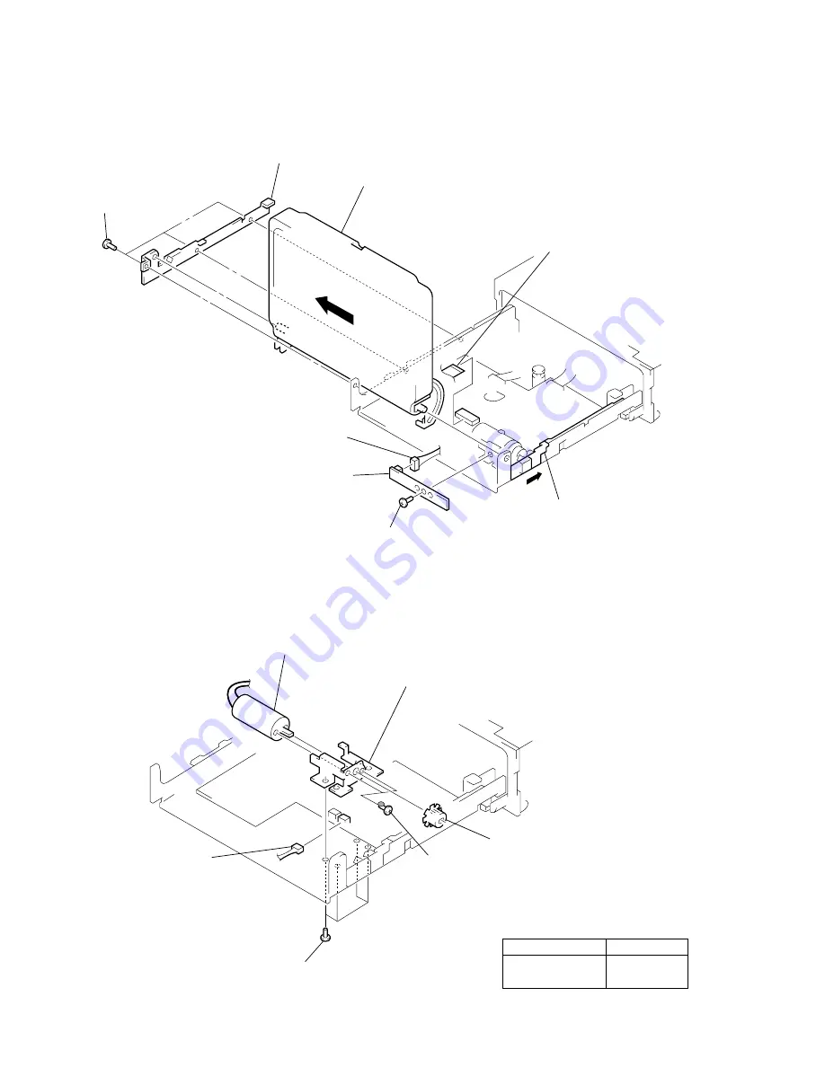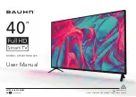
8
DC MOTOR (SMALL TYPE) (ANGLE) (M11)
C BOARD, MONITOR
5
three screws
(M2
×
3)
6
side plate
B
8
Remove the monitor in the
direction of arrow
B
.
1
flat cable 26P
(CN401)
A
7
Push the slider knob (R)
in the direction of arrow
A
.
4
C board
3
screw (M2
×
3)
2
connector
(CN11)
2
four screws
(M2
×
3
)
1
connector
(CN108)
4
two screws
(M2
×
3)
3
motor gear (monitor)
6
bracket
(monitor motor)
5
DC motor (small type)
(angle) (M11)
B
Note: When installing these screws
and DC motor, apply a drop
of screw lock G (1401B).
Part Name
Part No.
SCREW LOCK G
7-432-114-11
(1401B)
Содержание XT-991V
Страница 14: ...14 MEMO ...
Страница 19: ...19 19 XTL 75V 6 5 SCHEMATIC DIAGRAM B Board Page 22 Page 22 ...
Страница 26: ...26 26 XTL 75V 6 13 PRINTED WIRING BOARD G Board See page 17 for IC Circuit Boards Location Page 20 ...
Страница 29: ...29 29 XTL 75V 6 16 SCHEMATIC DIAGRAM PANEL Board Page 23 ...


